Nissan Juke F15. Instruction — part 1231
TM-114
< UNIT DISASSEMBLY AND ASSEMBLY >
[6MT: RS6F52H]
TRANSAXLE ASSEMBLY
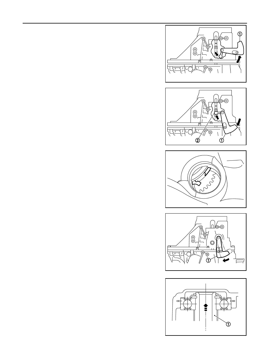
c.
With shifter lever A (1) held in the position shown, temporarily
assemble transaxle case to clutch housing.
CAUTION:
Do not damage striking rod oil seal.
NOTE:
Make sure to hold shifter lever A in the position shown. Other-
wise transaxle case cannot be installed to clutch housing.
d. While rotating shifter lever A (1) in the direction of the arrow
shown, assemble transaxle case to clutch housing.
e. Accessing from the bore plug hole, expand snap ring at main-
shaft rear bearing so that the ring catches the periphery of main-
shaft rear bearing.
f.
Temporarily tighten transaxle case bolts.
2. Shift the shifter lever A to 2nd gear position.
NOTE:
• The 2nd gear position is attained when shifter lever A (1) is in
the position shown.
• When transaxle is shifted to the 2nd gear position, mainshaft
assembly (1) is lifted.
PCIB1808E
2
: shifter lever B
PCIB1929E
PCIB1840E
PCIB1809E
PCIB1923E
TRANSAXLE ASSEMBLY
TM-115
< UNIT DISASSEMBLY AND ASSEMBLY >
[6MT: RS6F52H]
C
E
F
G
H
I
J
K
L
M
A
B
TM
N
O
P
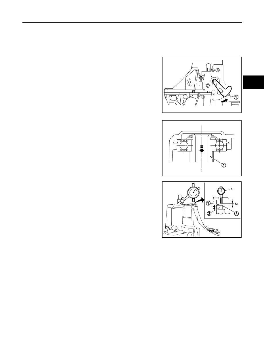
3. Seat snap ring in the groove on mainshaft rear bearing. If snap ring is not seated in the groove on main-
shaft rear bearing, remove transaxle case and repeat the procedure 1 from step c.
4. Shift the shifter lever A to 1st gear position, and then shift it to 2nd gear position. Repeat 3 times.
NOTE:
• The mainshaft rear bearing position will be stabilized by shifting between 1st gear position and 2nd gear
position alternately.
• The 1st gear position is attained when shifter lever A (1) is in
the position shown.
• When transaxle is shifted to the 1st gear position, mainshaft
assembly (1) is declined.
5. Set the dial indicator (A) to dummy adjusting shim (1) through
the bore plug hole.
PCIB1881E
PCIB1934E
2
: Mainshaft rear bearing
3
: Snap ring
PCIB1827E
TM-116
< UNIT DISASSEMBLY AND ASSEMBLY >
[6MT: RS6F52H]
TRANSAXLE ASSEMBLY
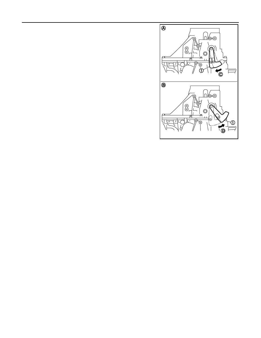
6. Shift the shifter lever A (1) to 2nd gear position (A), and then
rotate it in the direction of the arrow (C) shown until it stops.
Using this position as the reference point, measure the amount
of movement when shifting shifter lever A to 1st gear position (B)
and rotating it in the direction of the arrow (D) shown until it
stops. This measurement is the (M) dimension.
7. When measurement (M) is 0 - 0.06 mm (0 - 0.0024 in), adjust-
ment terminates, and the dummy adjusting shim becomes regu-
lar adjusting shim. Select adjusting shim from the computed
expressions when measurement (M) is over 0.06 mm (0.0024
in).
PCIB1935E
INPUT SHAFT AND GEARS
TM-117
< UNIT DISASSEMBLY AND ASSEMBLY >
[6MT: RS6F52H]
C
E
F
G
H
I
J
K
L
M
A
B
TM
N
O
P
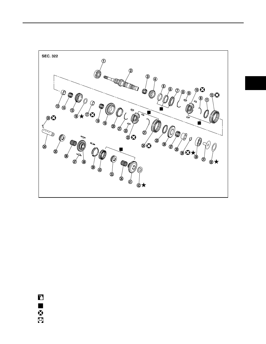
INPUT SHAFT AND GEARS
Exploded View
INFOID:0000000012200824
1.
Input shaft front bearing
2.
Input shaft
3.
3rd needle bearing
4.
3rd input gear
5.
3rd inner baulk ring
6.
3rd synchronizer cone
7.
3rd outer baulk ring
8.
3rd-4th spread spring
9.
3rd-4th shifting insert
10. 3rd-4th synchronizer hub
11. 4th baulk ring
12. 3rd-4th coupling sleeve
13. 4th input gear bushing
14. 4th needle bearing
15. 4th input gear
16. Thrust washer
17. 5th input gear bushing
18. 5th needle bearing
19. 5th input gear
20. 5th baulk ring
21. 5th-6th spread spring
22. 5th-6th shifting insert
23. 5th-6th synchronizer hub
24. 5th-6th coupling sleeve
25. 6th baulk ring
26. 6th input gear
27. 6th needle bearing
28. 6th input gear bushing
29. Snap ring
30. Input shaft rear bearing
31. Oil channel
32. Input shaft rear bearing adjusting
shim
33. Retaining pin
34. Reverse idler shaft
35. Thrust needle bearing
36. Reverse idler gear needle bear-
ing
37. Reverse insert spring
38. Reverse idler gear (front)
39. Reverse baulk ring
40. Reverse coupling sleeve
41. Reverse idler gear (rear)
42. Reverse idler gear adjusting shim
: Apply gear oil.
: Replace the parts as a set.
: Always replace after every disassembly.
: N·m (kg-m, ft-lb)
PCIB1888E
Нет комментариевНе стесняйтесь поделиться с нами вашим ценным мнением.
Текст