Nissan Juke F15. Instruction — part 63

BCS
SYSTEM
BCS-7
< SYSTEM DESCRIPTION >
[WITH INTELLIGENT KEY SYSTEM]
C
D
E
F
G
H
I
J
K
L
B
A
O
P
N
BODY CONTROL SYSTEM : Fail-safe
INFOID:0000000012965013
FAIL-SAFE CONTROL BY DTC
BCM performs fail-safe control when any DTC are detected.
Front wiper and washer system
WW-7, "FRONT WIPER AND WASHER SYSTEM : System Dia-
gram"
Rear wiper and washer system
WW-10, "REAR WIPER AND WASHER SYSTEM : System Dia-
gram"
Warning chime system
WCS-7, "WARNING CHIME SYSTEM : System Diagram"
Power door lock system
Nissan Vehicle Immobilizer System (NVIS) - NATS
SEC-13, "NISSAN VEHICLE IMMOBILIZER SYSTEM-NATS :
System Diagram"
Vehicle security system
Theft warning alarm
SEC-16, "VEHICLE SECURITY SYSTEM : System Diagram"
Panic alarm
Rear window defogger system
•
DEF-7, "WITH AUTO A/C : System Diagram"
(With automatic
A/C)
•
DEF-7, "WITHOUT AUTO A/C : System Diagram"
(Without au-
tomatic A/C)
Intelligent Key system/engine start system
DLK-13, "INTELLIGENT KEY SYSTEM : System Diagram"
Back door opener system
Air conditioning control system
Automatic A/C
Instruction A/C
Power window system
PWC-9, "POWER WINDOW SYSTEM : System Diagram"
Retained accessory power (Retain power operation)
PWC-9, "POWER WINDOW SYSTEM : System Description"
Tire pressure monitoring system (TPMS)
System
Reference
Display contents of CONSULT
Fail-safe
Cancellation
B2192: ID DISCORD BCM-ECM
Inhibit engine cranking
Erase DTC
B2193: CHAIN OF BCM-ECM
Inhibit engine cranking
Erase DTC
B2195: ANTI-SCANNING
Inhibit engine cranking
Ignition switch ON
→ OFF
B2196: DONGLE NG
Inhibit engine cranking
Erase DTC
B2198: NATS ANTENNA AMP
Inhibit engine cranking
Erase DTC
B2608: STARTER RELAY
Inhibit engine cranking
500 ms after the following signal communication status becomes con-
sistent
• Starter motor relay control signal
• Starter relay status signal (CAN)
B260F: ENG STATE SIG LOST
Inhibit engine cranking
When any of the following conditions are fulfilled
• Power position changes to ACC
• Receives engine status signal (CAN)
B26F1: IGN RELAY OFF
Inhibit engine cranking
When the following conditions are fulfilled
• Ignition switch ON signal (CAN: Transmitted from BCM): ON
• Ignition switch ON signal (CAN: Transmitted from IPDM E/R): ON
B26F2: IGN RELAY ON
Inhibit engine cranking
When the following conditions are fulfilled
• Ignition switch ON signal (CAN: Transmitted from BCM): OFF
• Ignition switch ON signal (CAN: Transmitted from IPDM E/R): OFF
B26F3: START CONT RLY ON
Inhibit engine cranking
When the following conditions are fulfilled
• Starter control relay signal (CAN: Transmitted from BCM): OFF
• Starter control relay signal (CAN: Transmitted from IPDM E/R): OFF
BCS-8
< SYSTEM DESCRIPTION >
[WITH INTELLIGENT KEY SYSTEM]
SYSTEM
REAR WIPER MOTOR PROTECTION
BCM detects the rear wiper stopping position according to the rear wiper stop position signal.
When the rear wiper stop position signal does not change for more than 5 seconds while driving the rear
wiper, BCM stops power supply to protect the rear wiper motor.
Condition of cancellation
1. More than 1 minute is passed after the rear wiper stop.
2. Turn rear wiper switch OFF.
3. Operate the rear wiper switch or rear washer switch.
FAIL-SAFE CONTROL OF COMBINATION SWITCH READING FUNCTION CAUSED BY LOW
POWER SUPPLY VOLTAGE
If voltage of battery power supply lower, BCM maintains combination switch reading to the status when input
voltage is less than approximately 9 V.
NOTE:
When voltage of battery power supply is approximately 9 V or more, combination switch reading function
returns to normal operation.
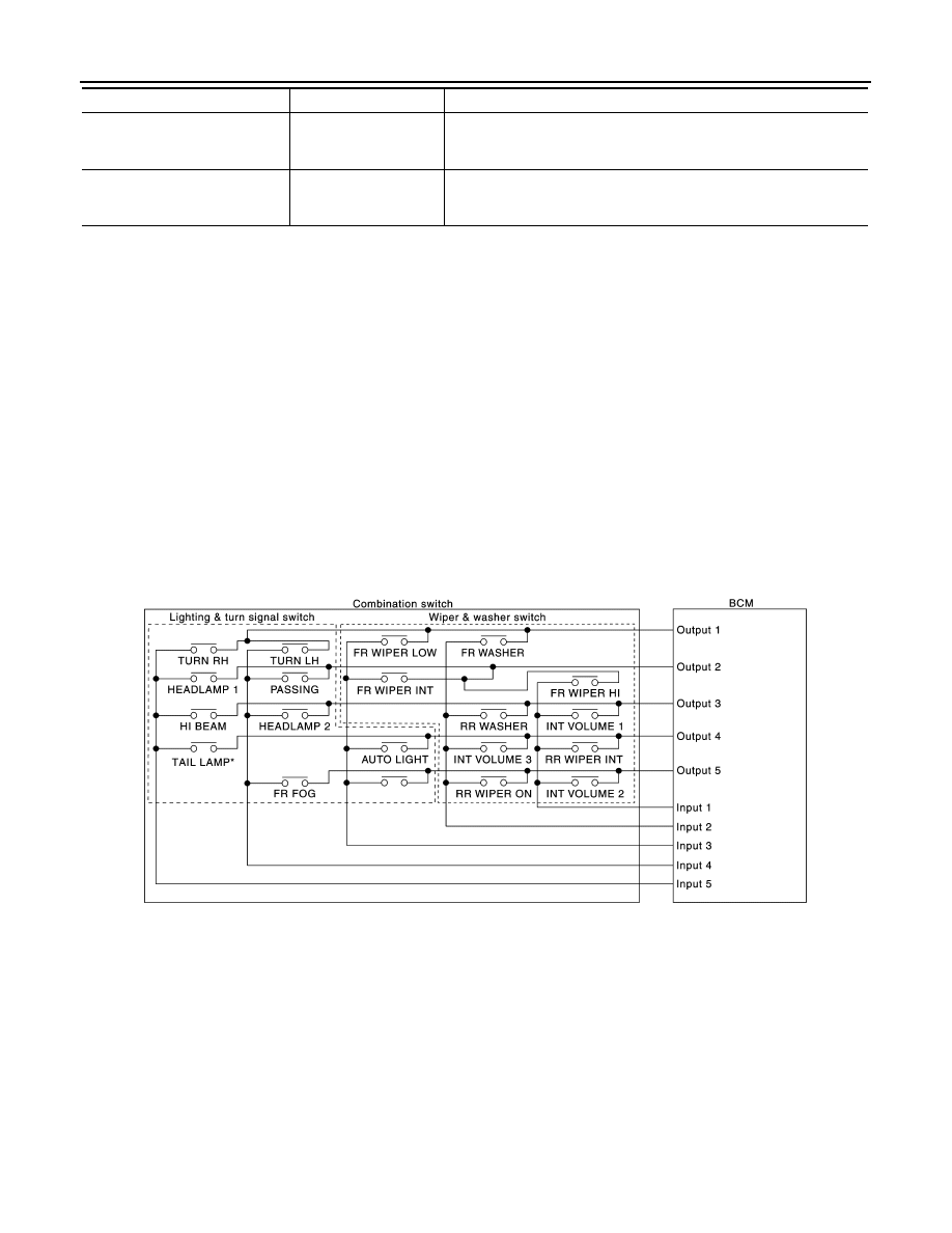
COMBINATION SWITCH READING SYSTEM
COMBINATION SWITCH READING SYSTEM : System Diagram
INFOID:0000000012200690
NOTE:
*: TAIL LAMP switch links lighting switch 1ST and 2ND positions.
COMBINATION SWITCH READING SYSTEM : System Description
INFOID:0000000012200691
OUTLINE
• BCM reads the status of the combination switch (light, turn signal, wiper and washer) and recognizes the
status of each switch.
• BCM has a combination of 5 output terminals (OUTPUT 1 - 5) and 5 input terminals (INPUT 1 - 5). It reads a
maximum of 20 switch status.
COMBINATION SWITCH MATRIX
B26F4: START CONT RLY OFF
Inhibit engine cranking
When the following conditions are fulfilled
• Starter control relay signal (CAN: Transmitted from BCM): ON
• Starter control relay signal (CAN: Transmitted from IPDM E/R): ON
B26F7: BCM
Inhibit engine cranking
by Intelligent Key sys-
tem
When room antenna and luggage room antenna functions normally
Display contents of CONSULT
Fail-safe
Cancellation
JMMIA0636GB
BCS
SYSTEM
BCS-9
< SYSTEM DESCRIPTION >
[WITH INTELLIGENT KEY SYSTEM]
C
D
E
F
G
H
I
J
K
L
B
A
O
P
N
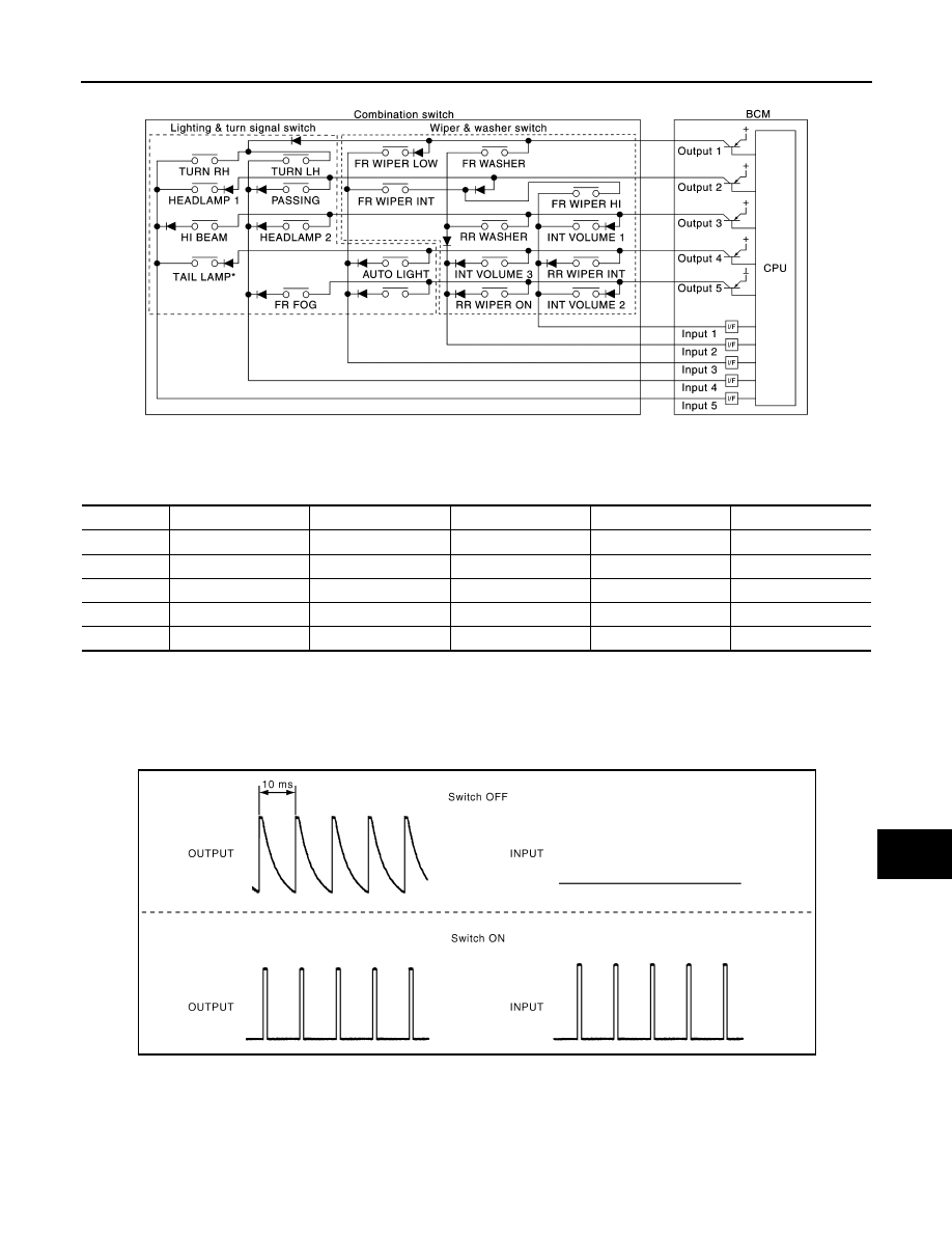
Combination switch circuit
NOTE:
*: TAIL LAMP switch links lighting switch 1ST and 2ND positions.
Combination switch INPUT-OUTPUT system list
NOTE:
Headlamp has a dual system switch.
COMBINATION SWITCH READING FUNCTION
Description
• BCM reads the status of the combination switch at 10 ms interval normally.
NOTE:
BCM reads the status of the combination switch at 60 ms interval when BCM is controlled at low power con-
sumption control mode.
• BCM operates as follows and judges the status of the combination switch.
- It operates the transistor on OUTPUT side in the following order: OUTPUT 1
→ 2 → 3 → 4 → 5, and outputs
voltage waveform.
JMMIA0637GB
System
INPUT 1
INPUT 2
INPUT 3
INPUT 4
INPUT 5
OUTPUT 1
—
FR WASHER
FR WIPER LOW
TURN LH
TURN RH
OUTPUT 2
FR WIPER HI
—
FR WIPER INT
PASSING
HEADLAMP 1
OUTPUT 3
INT VOLUME 1
RR WASHER
—
HEADLAMP 2
HI BEAM
OUTPUT 4
RR WIPER INT
INT VOLUME 3
AUTO LIGHT
—
TAIL LAMP
OUTPUT 5
INT VOLUME 2
RR WIPER ON
—
FR FOG
—
JPMIA0609GB
BCS-10
< SYSTEM DESCRIPTION >
[WITH INTELLIGENT KEY SYSTEM]
SYSTEM
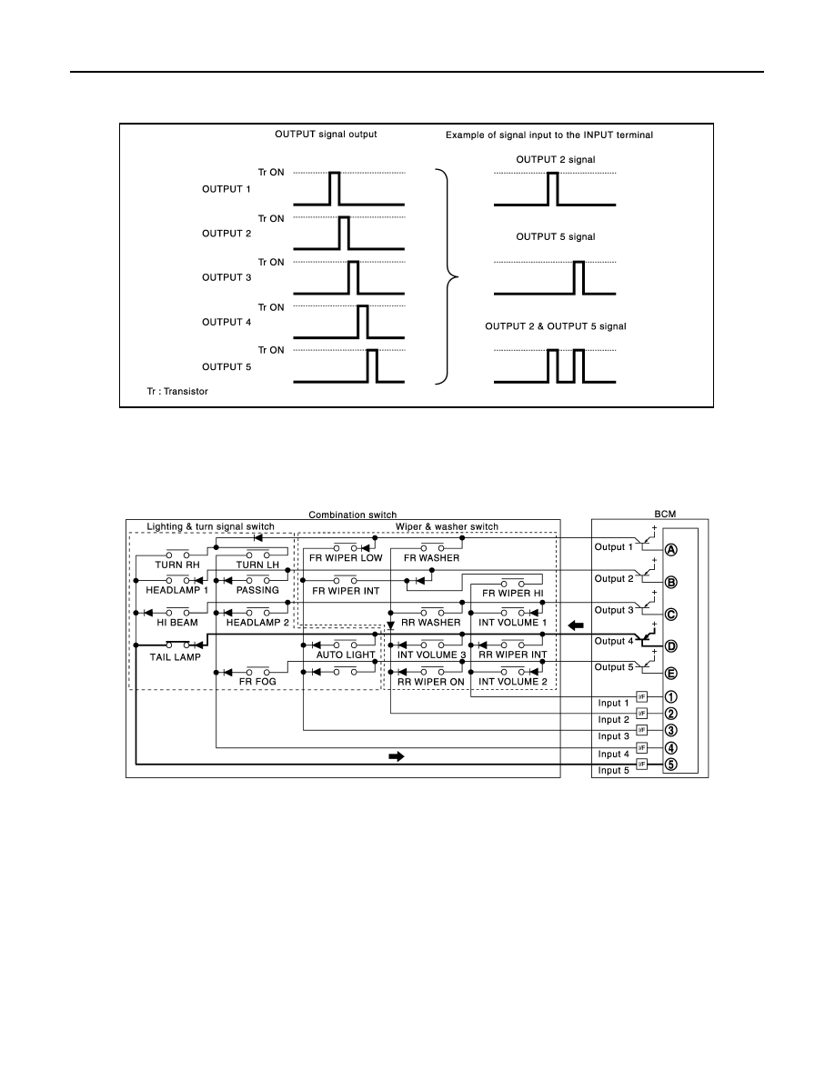
- The voltage waveform of OUTPUT corresponding to the formed circuit is input into the interface on INPUT
side if any (1 or more) switches are ON.
- It reads this change of the voltage as the status signal of the combination switch.
Operation Example
In the following operation example, the combination of the status signals of the combination switch is replaced
as follows: INPUT 1 - 5 to “1 - 5” and OUTPUT 1 - 5 to “A - E”.
Example 1: When a switch (TAIL LAMP switch) is turned ON
• The circuit between OUTPUT 4 and INPUT 5 is formed when the TAIL LAMP switch is turned ON.
• BCM detects the combination switch status signal “5D” when the signal of OUTPUT 4 is input to INPUT 5.
• BCM judges that the TAIL LAMP switch is ON when the signal “5D” is detected.
Example 2: When some switches (TURN RH switch, TAIL LAMP switch) are turned ON
JMMIA0326GB
JPMIA1545GB
Нет комментариевНе стесняйтесь поделиться с нами вашим ценным мнением.
Текст