Nissan Qashqai (2018 year). Manual — part 8
2-46
Instruments and controls
JVI1621X
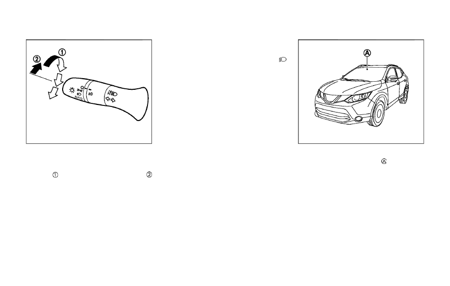
High beam assist operations:
To activate the high beam assist system,
turn the headlight switch to the AUTO
position
and push the lever forward
(high beam position). The high beam
assist indicator light in the meter will
illuminate while the headlights are turned
on.
If the high beam assist indicator light
does not illuminate in the above condi-
tion, it may indicate that the system is not
functioning properly. It is recommended
you have the system checked by a
NISSAN dealer.
When the vehicle speed lowers to less
than approximately 13 MPH (20 km/h), the
headlight remains the low beam.
To turn off the high beam assist system,
turn the headlight switch to the
position or select the low beam position
by placing the lever in the neutral posi-
tion.
JVS1079X
Ambient image sensor maintenance:
The ambient image sensor
for the high
beam assist system is located in front of
the inside mirror. To keep the proper
operation of the high beam assist system
and prevent a system malfunction, be
sure to observe the following:
. Always keep the windshield clean.
. Do not attach a sticker (including
transparent material) or install an
accessory near the ambient image
sensor.
. Do not strike or damage the areas
around the ambient image sensor. Do
not touch the sensor lens that is
located on the ambient image sensor.
If the ambient image sensor is damaged
due to an accident, it is recommended
you contact a NISSAN dealer.
Battery saver system
. When the headlight switch is in the
or
position while the ignition
switch is in the ON position, the lights
will automatically turn off within a
period of time after the ignition switch
has been placed in the OFF position.
. When the headlight switch remains in
the
or
position after the lights
automatically turn off, the lights will
turn on when the ignition switch is
placed in the ON position.
CAUTION
. When you turn on the headlight
switch again after the lights auto-
matically turn off, the lights will
not turn off automatically. Be
sure to turn the light switch to
the OFF position when you leave
the vehicle for extended periods
of time, otherwise the battery will
be discharged.
. Never leave the light switch on
when the engine is not running
for extended periods of time even
if the headlights turn off auto-
matically.
Daytime Running Light (DRL) sys-
tem
The LED portion of the headlights auto-
matically illuminate at 100% intensity
when the engine is started and the
parking brake released. The LED Daytime
Running Light (DRL) operate with the
headlight switch in the OFF position or
in the
position. When you turn the
headlight switch to the
position for
full illumination, the LED lights switch
from LED DRL to the park function.
If the parking brake is applied before the
engine is started, the LED DRL do not
illuminate. The LED DRL illuminate when
the parking brake is released. The LED
DRL will remain on until the ignition
switch is placed in the OFF position.
It is necessary at dusk to turn the head-
light switch ON for interior controls and
switches to illuminate, as those remain
OFF while the switch is in the OFF
position.
WARNING
When the LED DRL system is active,
tail lights on your vehicle are not on.
It is necessary at dusk to turn on
your headlights. Failure to do so
could cause an accident injuring
yourself and others.
Instruments and controls
2-47
2-48
Instruments and controls
JVI1591X
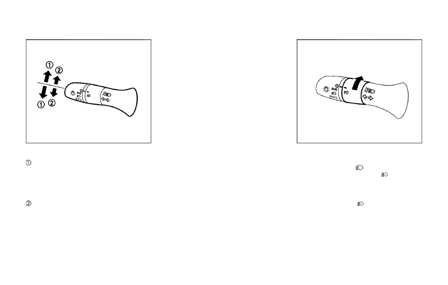
TURN SIGNAL SWITCH
Turn signal
Move the lever up or down to signal the
turning direction. When the turn is com-
pleted, the turn signals cancel automati-
cally.
Lane change signal
Move the lever up or down until the turn
signal begins to flash, but the lever does
not latch, to signal a lane change. Hold
the lever until the lane change is com-
pleted.
Move the lever up or down until the turn
signal begins to flash, but the lever does
not latch, and release the lever. The turn
signal will automatically flash three times.
Choose the appropriate method to signal
a lane change based on road and traffic
conditions.
JVI0980X
FOG LIGHT SWITCH (if so equipped)
To turn the fog lights on, turn the head-
light switch to the
position, then turn
the fog light switch to the
position.
To turn the fog lights on with the head-
light switch in the AUTO position, the
headlights must be on, then turn the fog
light switch to the
position.
To turn them off, turn the fog light switch
to the OFF position.
The headlights must be on for the fog
lights to operate. The fog lights automa-
tically turn off when the high beam
headlights are selected.
JVI1569X
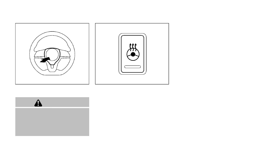
To sound the horn, push the center pad
area of the steering wheel.
WARNING
Do not disassemble the horn. Doing
so could affect proper operation of
the supplemental front air bag sys-
tem. Tampering with the supple-
mental front air bag system may
result in serious personal injury.
JVI1592X
The heated steering wheel system is
designed to operate only when the sur-
face temperature of the steering wheel is
below 68°F (20°C).
Push the heated steering wheel switch to
warm the steering wheel after the engine
starts. The indicator light on the switch
will illuminate.
If the surface temperature of the steering
wheel is below 68°F (20°C), the system will
heat the steering wheel and cycle off and
on to maintain a temperature above 68°F
(20°C). The indicator light will remain on
as long as the system is on.
Push the switch again to turn the heated
steering wheel system off manually. The
indicator light will turn off.
NOTE:
If the surface temperature of the steer-
ing wheel is above 68°F (20°C) when the
switch is turned on, the system will not
heat the steering wheel. This is not a
malfunction.
Instruments and controls
2-49
HORN
HEATED STEERING WHEEL (if so equipped)
2-50
Instruments and controls
WARNING
Do not use or allow occupants to use
the seat heater if you or the occu-
pants cannot monitor elevated seat
temperatures or have an inability to
feel pain in body parts that contact
the seat. Use of the seat heater by
such people could result in serious
injury.
CAUTION
. The battery could run down if the
seat heater is operated while the
engine is not running.
. Do not use the seat heater for
extended periods or when no one
is using the seat.
. Do not put anything on the seat
which insulates heat, such as a
blanket, cushion, seat cover, etc.
Otherwise, the seat may become
overheated.
. Do not place anything hard or
heavy on the seat or pierce it with
a pin or similar object. This may
result in damage to the heater.
. Any liquid spilled on the heated
seat should be removed immedi-
ately with a dry cloth.
. When cleaning the seat, never use
gasoline, thinner, or any similar
materials.
. If any malfunctions are found or
the heated seat does not operate,
turn the switch off and have the
system checked. It is recom-
mended you visit a NISSAN dealer
for this service.
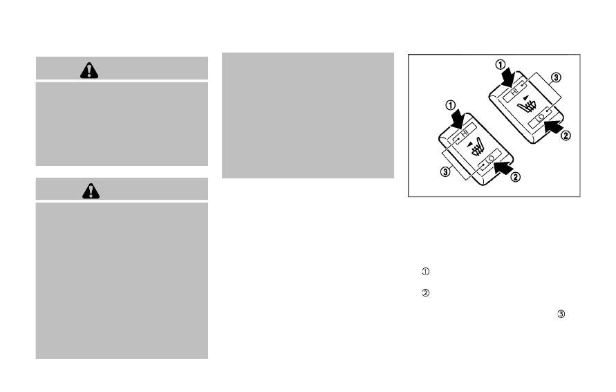
JVR0322X
The seats are warmed by built-in heaters.
The switches located on the center con-
sole can be operated independently of
each other.
1.
Start the engine.
2. Select heat range.
For high-speed heating, push the HI
(High) side of the switch.
For low-speed heating, push the LO
(Low) side of the switch.
The indicator light on the switch
will
illuminate when the heater is on.
3. To turn off the heater, return the
switch to the level position. Make sure
the indicator light goes off.
HEATED SEATS (if so equipped)
The heater is controlled by a thermo-
stat, automatically turning the heater
on and off. The indicator light will
remain on as long as the switch is on.
When the vehicle’s interior is warmed,
or before you leave the vehicle, be
sure to turn off the switch.
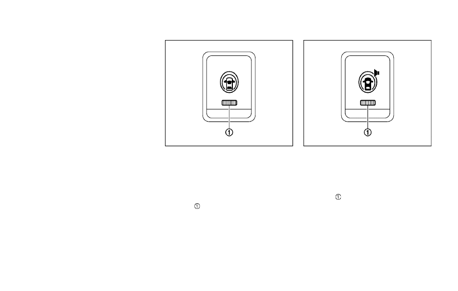
JVI1593X
The Intelligent Lane Intervention (I-LI)
switch is used to turn on and off the I-LI
system.
The I-LI system must be turned on with
the I-LI switch every time the ignition is
placed in the ON position.
When the I-LI switch is turned off, the
indicator
on the switch is off.
The I-LI system warns the driver with a
warning indicator and a chime, and helps
assist the driver to return the vehicle to
the center of the traveling lane by apply-
ing the brakes to the left or right wheels
individually (for a short period of time). For
additional information, see “Intelligent
Lane Intervention (I-LI)” (P.5-37).
JVI1594X
The Blind Spot Warning (BSW) switch is
used to temporarily turn on and off the
BSW system that is activated using the
settings menu of the vehicle information
display.
When the BSW switch is turned off, the
indicator
on the switch is off. The
indicator will also be off if the BSW system
is deactivated using the vehicle informa-
tion display.
The BSW system helps alert the driver of
other vehicles in adjacent lanes when
changing lanes. For additional informa-
tion, see “Blind Spot Warning (BSW)” (P.5-
42).
Instruments and controls
2-51
INTELLIGENT LANE INTERVENTION
(I-LI) SWITCH (if so equipped)
BLIND SPOT WARNING (BSW)
SWITCH (if so equipped)
2-52
Instruments and controls
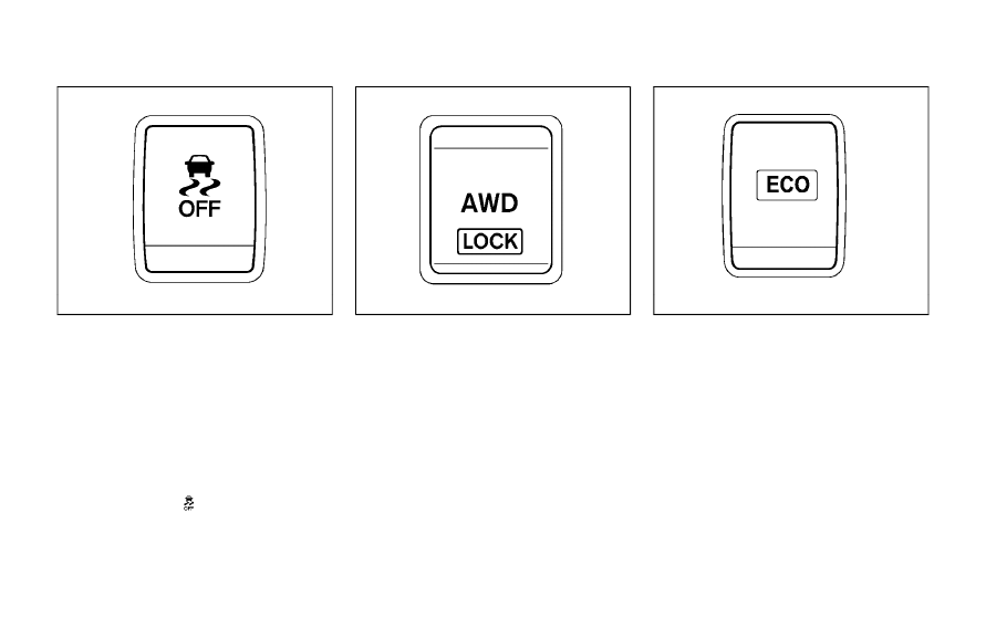
SIC4544
The vehicle should be driven with the
Vehicle Dynamic Control (VDC) system on
for most driving conditions.
If the vehicle is stuck in mud or snow, the
VDC system reduces the engine output to
reduce wheel spin. The engine speed will
be reduced even if the accelerator is
depressed to the floor. If maximum en-
gine power is needed to free a stuck
vehicle, turn the VDC system off.
To turn off the VDC system, push the VDC
OFF switch. The
indicator light will
illuminate.
Push the VDC OFF switch again or restart the
engine to turn on the system. (See “Vehicle
Dynamic Control (VDC) system” (P.5-108).)
JVI1595X
The Intelligent 4x4 LOCK switch is located
on the instrument panel. The AWD LOCK
indicator light will illuminate when the
switch is turned on. For additional infor-
mation, refer to “Intelligent 4x4” (P.5-100).
Each time you push the switch, the AWD
mode will switch: AUTO ? LOCK ? AUTO.
JVS0185X
The ECO mode system helps to enhance
the fuel economy by controlling the
engine and CVT operation (for CVT mod-
els) automatically to avoid rapid accelera-
tion.
To turn on the ECO mode system, push
the ECO switch. The ECO mode indicator
appears on the meter.
To turn off the ECO mode, push the ECO
switch again. The ECO mode indicator will
turn off.
. The ECO mode system cannot be
turned off while the accelerator pedal
is depressed even if the ECO switch is
pushed to OFF. Release the accelera-
tor pedal to turn off the ECO mode
VEHICLE DYNAMIC CONTROL (VDC)
OFF SWITCH
INTELLIGENT 4X4 LOCK SWITCH (if
so equipped)
ECO MODE SWITCH
system.
. The ECO mode system will turn off
automatically if a malfunction occurs
in the system.
. Turn off the ECO mode system when
acceleration is required such as when:
— driving with a heavy load of pas-
sengers or cargo in the vehicle
— driving on a steep uphill slope
JVI0878X
The power outlet is located in the instru-
ment panel.
CAUTION
. The outlet and plug may be hot
during or immediately after use.
. Do not use with accessories that
exceed a 12 volt, 120W (10A)
power draw. Do not use double
adapters or more than one elec-
trical accessory.
. Use power outlet with the engine
running to avoid discharging the
vehicle battery.
. Avoid using power outlet when
the air conditioner, headlights or
rear window defroster is on.
. This power outlet is not designed
for use with a cigarette lighter
unit.
. Push the plug in as far as it will
go. If good contact is not made,
the plug may overheat or the
internal temperature fuse may
open.
. Before inserting or disconnecting
a plug, be sure the electrical
accessory being used is turned
OFF.
. When not in use, be sure to close
the cap. Do not allow water or any
liquid to contact the outlet.
Instruments and controls
2-53
POWER OUTLET
2-54
Instruments and controls
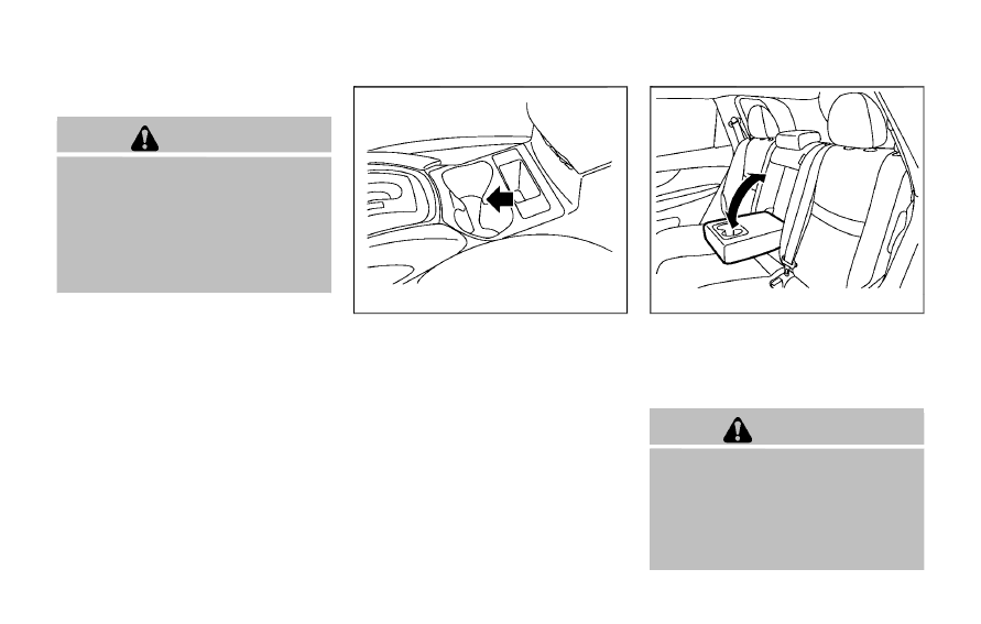
CUP HOLDERS
CAUTION
. Avoid abrupt starting and braking
when the cup holder is being
used to prevent spilling the drink.
If the liquid is hot, it can scald you
or your passenger.
. Use only soft cups in the cup
holder. Hard objects can injure
you in an accident.
JVI1601X
Center console
Front
JVI0873X
Rear seat (if so equipped)
The rear cup holders are located in the
rear fold-down armrest.
SOFT BOTTLE HOLDERS
CAUTION
. Do not use bottle holder for any
other objects that could be
thrown about in the vehicle and
possibly injure people during
sudden braking or an accident.
. Do not use bottle holder for open
liquid containers.
STORAGE
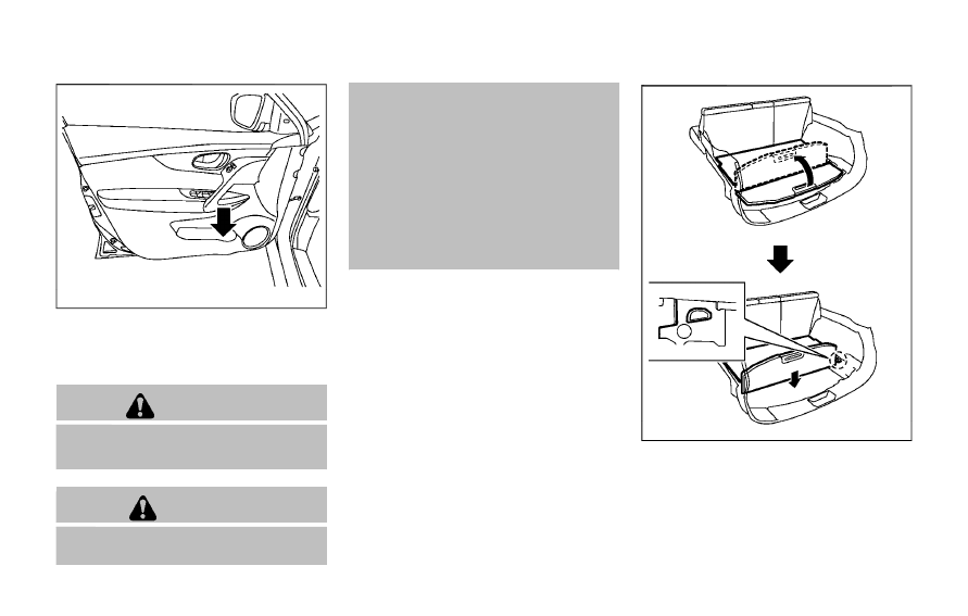
JVI0884X
Door (front and rear)
CARGO AREA (if so equipped)
You can use the cargo area in diverse
ways using the flexible luggage boards.
WARNING
Do not put objects heavier than 110
lbs (50 kg) on the load floor.
CAUTION
. Do not push the front edge of the
luggage board forcibly. Doing so
may cause the luggage board to
be tilted, resulting in personal
injury.
. Do not handle the luggage board
forcibly as this may deform it.
. While in the upper position, do
not recline the seatbacks.
. Do not place cargo higher than
the seatbacks. In a sudden stop
or collision, unsecured cargo
could cause personal injury.
NOTE:
The diversity of the cargo area may be
restricted depending on the equipment
of each vehicle.
JVI1620X
1.
Pull the outer board upward to 90°.
2. Push down the board until it stops.
Instruments and controls
2-55
2-56
Instruments and controls
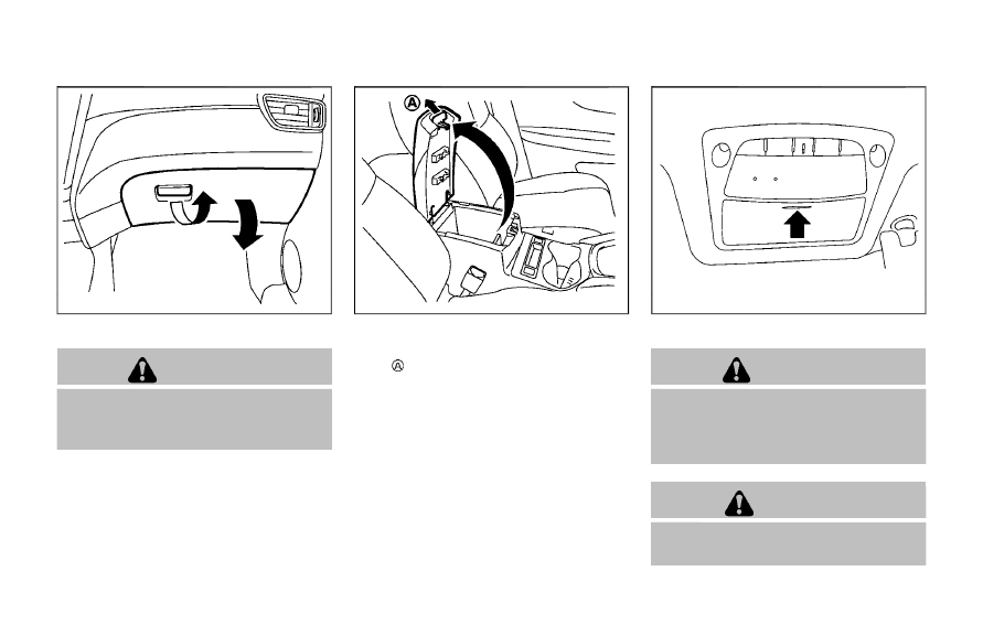
JVI0888X
GLOVE BOX
WARNING
Keep glove box lid closed while driv-
ing to help prevent injury in an
accident or a sudden stop.
To open the glove box, pull the handle.
To close, push the lid in until the lock
latches. The glove box light illuminates
when the headlight switch is turned on.
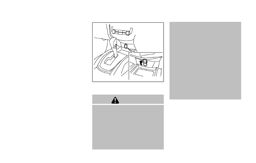
JVI1685X
CONSOLE BOX
To open the console box lid, push up the
knob
and pull up the lid.
To close, push the lid down until the lock
latches.
JVI0619X
SUNGLASSES HOLDER
WARNING
Keep the sunglasses holder closed
while driving to avoid obstructing
the driver’s view and to help prevent
an accident.
CAUTION
. Do not use for anything other
than sunglasses.
. Do not leave sunglasses in the
sunglasses holder while parking
in direct sunlight. The heat may
damage the sunglasses.
To open the sunglasses holder, push and
release. Only store one pair of sunglasses
in the holder.
SIC4348
CARD HOLDER (driver’s side)
Slide a card in the card holder.
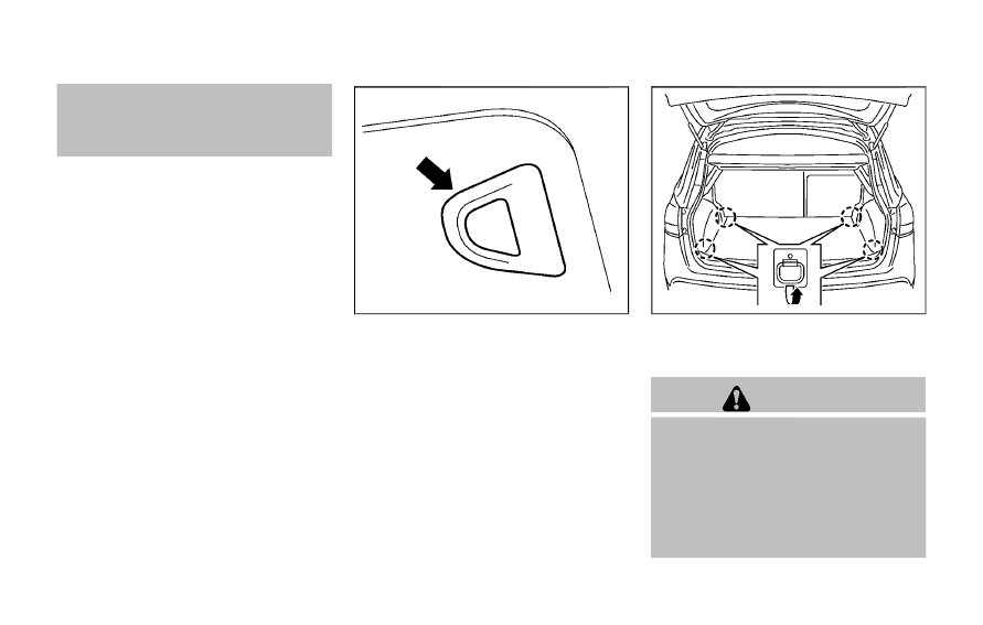
JVI1686X
Cargo area
LUGGAGE HOOKS
To use the hook, pull it up as illustrated.
WARNING
. Always make sure that the cargo
is properly secured. Use the sui-
table ropes and hooks.
. Unsecured cargo can become
dangerous in an accident or sud-
den stop.
. Do not apply a total load of more
than 22 lb (10 kg) to a single hook.
Instruments and controls
2-57
2-58
Instruments and controls
JVI1336X
Cargo area (hooks for shopping bags, etc.)
WARNING
Do not apply a total load of more
than 7 lb (3 kg) to the hook.
JVI1334X
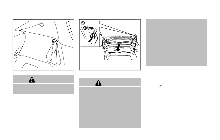
PARCEL SHELF
WARNING
. Never put anything on the parcel
shelf, no matter how small. Any
object on it could cause an injury
in case of an accident or if the
brakes are applied suddenly.
. Do not leave the parcel shelf in
position when it is disengaged
from the grooves.
. Properly secure all cargo to help
prevent it from sliding or shifting.
Do not place cargo higher than
the seatbacks. In a sudden stop
or collision, unsecured cargo
could cause personal injury
. The child restraint top tether
strap may be damaged by con-
tact with the parcel shelf or items
in the cargo area. Remove the
parcel shelf from the vehicle or
store it in its storage space. Also,
secure any lose items in the cargo
area. Your child could be seriously
injured or killed in a collision if the
top tether strap is damaged.
Removal
1.
Open the liftgate. (See “Liftgate” (P.3-
25).)
2. Detach both of the ropes (left and
right)
from the inside of the liftgate.
3. Detach the parcel shelf by simply
pulling it rearwards through the lift-
gate opening.
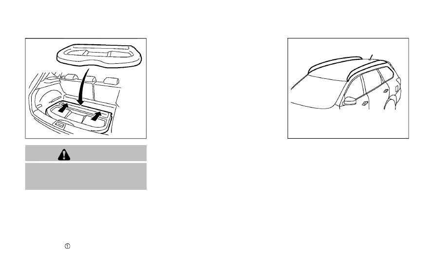
JVI1335X
CAUTION
Make sure the parcel shelf is care-
fully stored when not in use in order
to prevent any damage.
Installation
1.
Open the liftgate.
2. Insert the parcel shelf by pushing it
forwards as far as possible through
the liftgate opening.
3. Attach the corresponding ropes to
each side
of the liftgate.
4. Close the liftgate.
JVI0889X
Do not apply any load directly to the roof
side rails. Cross bars must be installed
before applying load/cargo/luggage to
the roof of the vehicle. Genuine NISSAN
accessory cross bars are available
through a NISSAN dealer. It is recom-
mended that you visit a NISSAN dealer for
additional information.
The service load capacity for the roof side
rails is 150 lb (68 kg), however do not
exceed the accessory cross bars load
capacity.
Be careful that your vehicle does not
exceed the Gross Vehicle Weight Rating
(GVWR) or its Gross Axle Weight Rating
(GAWR front and rear). The GVWR and
Instruments and controls
2-59
ROOF RACK (if so equipped)
2-60
Instruments and controls
GAWR are located on the F.M.V.S.S. or C.V.
M.S.S. certification label (located on the
driver’s door pillar). For additional infor-
mation regarding GVWR and GAWR, refer
to “Vehicle loading information” (P.10-11).
WARNING
. Always install the cross bars onto
the roof side rails before loading
cargo of any kind. Loading cargo
directly onto the roof side rails or
the vehicle’s roof may cause ve-
hicle damage.
. Drive extra carefully when the
vehicle is loaded at or near the
cargo carrying capacity, espe-
cially if the significant portion of
that load is carried on the cross
bars.
. Heavy loading of the cross bars
has the potential to affect the
vehicle stability and handling
during sudden or unusual hand-
ling maneuvers.
. Roof rack cross bars should be
evenly distributed.
. Do not exceed maximum roof
rack cross bars load.
. Properly secure all cargo with
ropes or straps to help prevent it
from sliding or shifting. In a sud-
den stop or collision, unsecured
cargo could cause personal in-
jury.
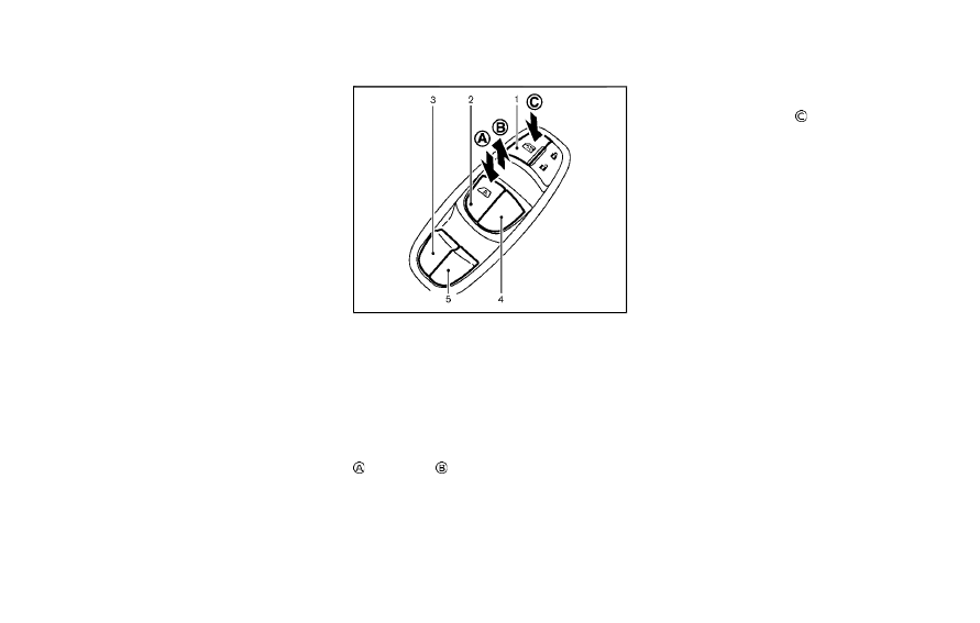
POWER WINDOWS
WARNING
. Make sure that all passengers
have their hands, etc. inside the
vehicle while it is in motion and
before closing the windows. Use
the window lock switch to pre-
vent unexpected use of the
power windows.
. To help avoid risk of injury or
death through unintended opera-
tion of the vehicle and or its
systems, including entrapment
in windows or inadvertent door
lock activation, do not leave chil-
dren, people who require the
assistance of others or pets un-
attended in your vehicle. Addi-
tionally, the temperature inside a
closed vehicle on a warm day can
quickly become high enough to
cause a significant risk of injury
or death to people and pets.
The power windows operate when the
ignition switch is in the ON position, or for
about 45 seconds after the ignition
switch is placed in the OFF position. If
the driver’s or front passenger’s door is
opened during this period of about 45
WINDOWS
seconds, power to the windows is can-
celed.
SIC4533
1.
Window lock button
2.
Driver side window
3.
Rear left passenger side window
4.
Front passenger side window
5.
Rear right passenger side window
Main power window switch (driver’s
side)
To open or close the window, push down
or pull up
the switch and hold it. The
main switch (driver side switches) will
open or close all the windows.
Locking passengers’ windows
When the lock button
is pushed in, only
the driver side window can be opened or
closed. Push it in again to cancel.
Instruments and controls
2-61
Нет комментариевНе стесняйтесь поделиться с нами вашим ценным мнением.
Текст