Nissan Murano Z51. Instruction — part 879

B2578, B2579 IN-VEHICLE SENSOR
HAC-171
< DTC/CIRCUIT DIAGNOSIS >
[WITH 7 INCH DISPLAY]
C
D
E
F
G
H
J
K
L
M
A
B
HAC
N
O
P
NOTE:
If DTC is displayed along with DTC U1000 or U1010, first diagnose the DTC U1000 or U1010. Refer to
DTC CONFIRMATION PROCEDURE
1.
CHECK WITH SELF-DIAGNOSIS FUNCTION OF CONSULT-III
1.
Using CONSULT-III, perform “SELF-DIAGNOSIS RESULTS” of HVAC.
2.
Check if any DTC No. is displayed in the self-diagnosis results.
NOTE:
If DTC is displayed along with DTC U1000 or U1010, first diagnose the DTC U1000 or U1010. Refer to
Is DTC No.“B2578” or “B2579” displayed?
YES
>> Perform trouble diagnosis for the in-vehicle sensor. Refer to
HAC-171, "Diagnosis Procedure"
.
NO
>> INSPECTION END
Diagnosis Procedure
INFOID:0000000005514712
1.
CHECK VOLTAGE BETWEEN IN-VEHICLE SENSOR AND GROUND
1.
Disconnect in-vehicle sensor connector.
2.
Turn ignition switch ON.
3.
Check voltage between in-vehicle sensor harness connector and ground.
Is the inspection result normal?
YES
>> GO TO 2.
NO
>> GO TO 4.
2.
CHECK CIRCUIT CONTINUITY BETWEEN IN-VEHICLE SENSOR AND A/C AUTO AMP.
1.
Turn ignition switch OFF.
2.
Disconnect A/C auto amp. connector.
3.
Check continuity between in-vehicle sensor harness connector and A/C auto amp. harness connector.
Is the inspection result normal?
YES
>> GO TO 3.
NO
>> Repair harness or connector.
3.
CHECK IN-VEHICLE SENSOR
Check in-vehicle sensor. Refer to
HAC-172, "Component Inspection"
.
Is the inspection result normal?
YES
>> Replace A/C auto amp.
DTC
Items
(CONSULT-III screen terms)
Diagnostic item is detected when...
Possible cause
B2578
IN CAR SEN SHORT
Detected temperature at in-vehicle
sensor
−
44
°
C (
−
47
°
F) or less
• In-vehicle sensor
• A/C auto amp.
• Harness and connector
(In-vehicle sensor circuit is open,
or there is a short in the circuit)
B2579
IN CAR SEN OPEN
Detected temperature at in-vehicle
sensor 100
°
C (212
°
F) or more
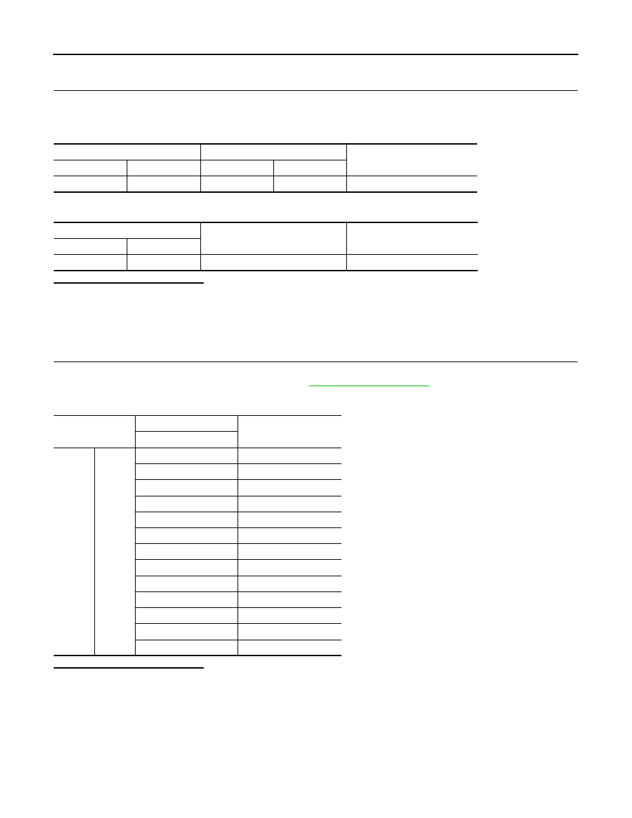
(+)
(
−
)
Voltage
In-vehicle sensor
—
Connector
Terminal
M41
1
Ground
Approx. 5 V
In-vehicle sensor
A/C auto amp.
Continuity
Connector
Terminal
Connector
Terminal
M41
2
M50
37
Existed
HAC-172
< DTC/CIRCUIT DIAGNOSIS >
[WITH 7 INCH DISPLAY]
B2578, B2579 IN-VEHICLE SENSOR
NO
>> Replace in-vehicle sensor.
4.
CHECK CIRCUIT CONTINUITY BETWEEN IN-VEHICLE SENSOR AND A/C AUTO AMP.
1.
Turn ignition switch OFF.
2.
Disconnect A/C auto amp. connector.
3.
Check continuity between in-vehicle sensor harness connector and A/C auto amp. harness connector.
4.
Check continuity between in-vehicle sensor harness connector and ground.
Is the inspection result normal?
YES
>> Replace A/C auto amp.
NO
>> Repair harness or connector.
Component Inspection
INFOID:0000000005514713
1.
CHECK IN-VEHICLE SENSOR
1.
Turn ignition switch OFF.
2.
Disconnect in-vehicle sensor connector. Refer to
.
3.
Check resistance between in-vehicle sensor terminals.
Is the inspection result normal?
YES
>> INSPECTION END
NO
>> Replace in-vehicle sensor.
In-vehicle sensor
A/C auto amp.
Continuity
Connector
Terminal
Connector
Terminal
M41
1
M50
36
Existed
In-vehicle sensor
—
Continuity
Connector
Terminal
M41
1
Ground
Not existed
Terminal
Condition
Resistance k
Ω
Temperature
°
C (
°
F)
1
2
−
15 (5)
12.73
−
10 (14)
9.92
−
5 (23)
7.80
0 (32)
6.19
5 (41)
4.95
10 (50)
3.99
15 (59)
3.24
20 (68)
2.65
25 (77)
2.19
30 (86)
1.81
35 (95)
1.51
40 (104)
1.27
45 (113)
1.07
B2581, B2582 INTAKE SENSOR
HAC-173
< DTC/CIRCUIT DIAGNOSIS >
[WITH 7 INCH DISPLAY]
C
D
E
F
G
H
J
K
L
M
A
B
HAC
N
O
P
B2581, B2582 INTAKE SENSOR
Description
INFOID:0000000005514714
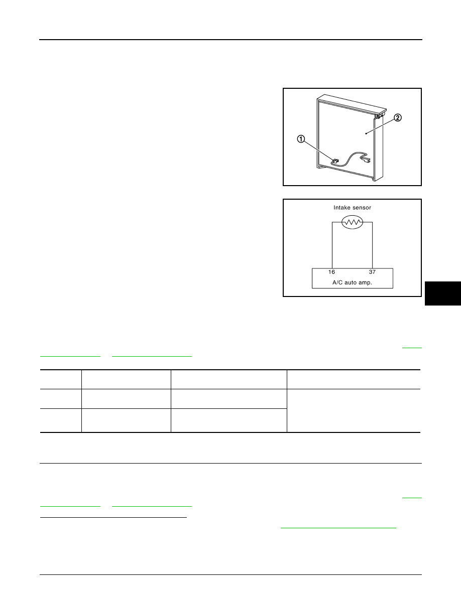
Intake Sensor
• The intake sensor (1) is located on the evaporator (2).
• It converts air temperature after it passes through the evaporator
into a resistance value which is then input to the A/C auto amp.
Intake Sensor Circuit
DTC Logic
INFOID:0000000005514715
DTC DETECTION LOGIC
NOTE:
If DTC is displayed along with DTC U1000 or U1010, first diagnose the DTC U1000 or U1010. Refer to
DTC CONFIRMATION PROCEDURE
1.
CHECK WITH SELF-DIAGNOSIS FUNCTION OF CONSULT-III
1.
Using CONSULT-III, perform “SELF-DIAGNOSIS RESULTS” of HVAC.
2.
Check if any DTC No. is displayed in the self-diagnosis results.
NOTE:
If DTC is displayed along with DTC U1000 or U1010, first diagnose the DTC U1000 or U1010. Refer to
Is DTC No.“B2581” or “B2582” displayed?
YES
>> Perform trouble diagnosis for the intake sensor. Refer to
HAC-173, "Diagnosis Procedure"
NO
>> INSPECTION END
Diagnosis Procedure
INFOID:0000000005514716
1.
CHECK VOLTAGE BETWEEN INTAKE SENSOR AND GROUND
JPIIA1351ZZ
JPIIA0614GB
DTC
Items
(CONSULT-III screen terms)
Diagnostic item is detected when...
Possible cause
B2581
EVAP TEMP SEN SHORT
Detected temperature at intake sensor
−
33
°
C (
−
27
°
F) or less
• Intake sensor
• A/C auto amp.
• Harness and connector
(Intake sensor circuit is open, or there is a
short in the circuit)
B2582
EVAP TEMP SEN OPEN
Detected temperature at intake sensor
69
°
C (156
°
F) or more

HAC-174
< DTC/CIRCUIT DIAGNOSIS >
[WITH 7 INCH DISPLAY]
B2581, B2582 INTAKE SENSOR
1.
Disconnect intake sensor connector.
2.
Turn ignition switch ON.
3.
Check voltage between intake sensor harness connector and ground.
Is the inspection result normal?
YES
>> GO TO 2.
NO
>> GO TO 4.
2.
CHECK CIRCUIT CONTINUITY BETWEEN INTAKE SENSOR AND A/C AUTO AMP.
1.
Turn ignition switch OFF.
2.
Disconnect A/C auto amp. connector.
3.
Check continuity between intake sensor harness connector and A/C auto amp. harness connector.
Is the inspection result normal?
YES
>> GO TO 3.
NO
>> Repair harness or connector.
3.
CHECK INTAKE SENSOR
Check intake sensor. Refer to
HAC-174, "Component Inspection"
Is the inspection result normal?
YES
>> Replace A/C auto amp.
NO
>> Replace intake sensor.
4.
CHECK CIRCUIT CONTINUITY BETWEEN INTAKE SENSOR AND A/C AUTO AMP.
1.
Turn ignition switch OFF.
2.
Disconnect A/C auto amp. connector.
3.
Check continuity between intake sensor harness connector and A/C auto amp. harness connector.
4.
Check continuity between intake sensor harness connector and ground.
Is the inspection result normal?
YES
>> Replace A/C auto amp.
NO
>> Repair harness or connector.
Component Inspection
INFOID:0000000005514717
1.
CHECK INTAKE SENSOR
1.
Turn ignition switch OFF.
2.
Disconnect intake sensor connector.
3.
Check resistance between intake sensor terminals.
(+)
(
−
)
Voltage
Intake sensor
—
Connector
Terminal
M42
1
Ground
Approx. 5 V
Intake sensor
A/C auto amp.
Continuity
Connector
Terminal
Connector
Terminal
M42
2
M50
37
Existed
Intake sensor
A/C auto amp.
Continuity
Connector
Terminal
Connector
Terminal
M42
1
M50
16
Existed
Intake sensor
—
Continuity
Connector
Terminal
M42
1
Ground
Not existed
Нет комментариевНе стесняйтесь поделиться с нами вашим ценным мнением.
Текст