Nissan Murano Z51. Instruction — part 1078
PCS-54
< DTC/CIRCUIT DIAGNOSIS >
[POWER DISTRIBUTION SYSTEM]
B2614 ACC RELAY
Component Inspection
INFOID:0000000005516979
1.
CHECK ACCESSORY RELAY
1.
Turn ignition switch OFF.
2.
Remove accessory relay.
3.
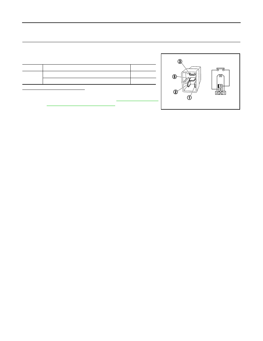
Check the continuity between accessory relay terminals.
Is the inspection result normal?
YES
>> INSPECTION END
NO
>> Replace accessory relay. Refer to
nector and Terminal Arrangement"
Terminals
Condition
Continuity
3 and 5
12 V direct current supply between terminals 1 and 2
Existed
No current supply
Not existed
PBIB0098E
PCS
B2615 BLOWER RELAY CIRCUIT
PCS-55
< DTC/CIRCUIT DIAGNOSIS >
[POWER DISTRIBUTION SYSTEM]
C
D
E
F
G
H
I
J
K
L
B
A
O
P
N
B2615 BLOWER RELAY CIRCUIT
Description
INFOID:0000000005516980
BCM controls the various electrical components and simultaneously supplies power according to the power
supply position.
BCM checks the power supply position internally.
DTC Logic
INFOID:0000000005516981
DTC DETECTION LOGIC
DTC CONFIRMATION PROCEDURE
1.
PERFORM DTC CONFIRMATION PROCEDURE
1.
Turn ignition switch ON under the following conditions, and wait for at least 1 second.
-
Selector lever is in the P or N position
-
Do not depress brake pedal
2.
Check “Self diagnostic result” with CONSULT-III.
Is DTC detected?
YES
>> Go to
NO
>> INSPECTION END
Diagnosis Procedure
INFOID:0000000005516982
1.
CHECK BLOWER RELAY POWER SUPPLY-1
1.
Turn ignition switch OFF.
2.
Disconnect blower relay.
3.
Check voltage between blower relay harness connector and ground.
Is the inspection result normal?
YES
>> GO TO 4.
NO
>> GO TO 2.
2.
CHECK BLOWER RELAY POWER SUPPLY-2
1.
Disconnect fuse block (J/B) connector.
2.
Check voltage between fuse block (J/B) harness connector and ground.
Is the inspection result normal?
DTC No.
Trouble diagnosis
name
DTC detecting condition
Possible cause
B2615
Blower relay circuit
BCM detects a difference of signal for 1 second or
more between the following information.
• Blower relay ON/OFF request
• Blower relay feedback
• Harness or connectors
(Blower relay circuit is open or
shorted)
• Blower relay
(+)
(–)
Condition
Voltage (V)
(Approx.)
Blower relay
Terminal
1
Ground
Ignition switch
OFF or ACC
0
ON
Battery voltage
(+)
(–)
Condition
Voltage (V)
(Approx.)
Fuse block (J/B)
Connector
Terminal
E103
6F
Ground
Ignition switch
OFF or ACC
0
ON
Battery voltage
PCS-56
< DTC/CIRCUIT DIAGNOSIS >
[POWER DISTRIBUTION SYSTEM]
B2615 BLOWER RELAY CIRCUIT
YES
>> Replace fuse block (J/B).
NO
>> GO TO 3.
3.
CHECK BLOWER RELAY POWER SUPPLY CIRCUIT-1
1.
Disconnect BCM connector.
2.
Check continuity between fuse block (J/B) harness connector and BCM harness connector.
3.
Check continuity between fuse block (J/B) harness connector and ground.
Is the inspection result normal?
YES
>> Replace BCM. Refer to
BCS-95, "Removal and Installation"
NO
>> Repair or replace harness.
4.
CHECK BLOWER RELAY GROUND CIRCUIT
Check continuity between blower relay harness connector and ground.
Is the inspection result normal?
YES
>> GO TO 5.
NO
>> Repair blower relay ground circuit.
5.
CHECK BLOWER RELAY POWER SUPPLY CIRCUIT-2
1.
Connect blower relay.
2.
Turn ignition switch ON.
3.
Check voltage between blower relay harness connector and ground.
Is the inspection result normal?
YES
>> GO TO 7.
NO
>> GO TO 6.
6.
CHECK BLOWER RELAY
PCS-57, "Component Inspection"
.
Is the inspection result normal?
YES
>> Replace fuse block (J/B).
NO
>> Replace blower relay. Refer to
PG-113, "Fuse, Connector and Terminal Arrangement"
7.
CHECK INTERMITTENT INCIDENT
GI-39, "Intermittent Incident"
>> INSPECTION END
Fuse block (J/B)
BCM
Continuity
Connector
Terminal
Connector
Terminal
E103
6F
M122
102
Existed
Fuse block (J/B)
Ground
Continuity
Connector
Terminal
E103
6F
Not existed
Blower relay
Ground
Continuity
Terminal
2
Existed
(+)
(–)
Voltage (V)
(Approx.)
Blower relay
Terminal
5
Ground
Battery voltage
PCS
B2615 BLOWER RELAY CIRCUIT
PCS-57
< DTC/CIRCUIT DIAGNOSIS >
[POWER DISTRIBUTION SYSTEM]
C
D
E
F
G
H
I
J
K
L
B
A
O
P
N
Component Inspection
INFOID:0000000005516983
1.
CHECK BLOWER RELAY
1.
Turn ignition switch OFF.
2.
Remove blower relay.
3.
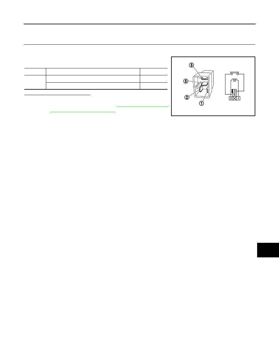
Check the continuity between blower relay terminals.
Is the inspection result normal?
YES
>> INSPECTION END
NO
>> Replace blower relay. Refer to
.
Terminals
Condition
Continuity
3 and 5
12 V direct current supply between terminals 1 and 2
Existed
No current supply
Not existed
PBIB0098E
Нет комментариевНе стесняйтесь поделиться с нами вашим ценным мнением.
Текст