Nissan Murano Z51. Instruction — part 982
LAN-134
< DTC/CIRCUIT DIAGNOSIS >
[CAN SYSTEM (TYPE 5)]
BCM BRANCH LINE CIRCUIT
BCM BRANCH LINE CIRCUIT
Diagnosis Procedure
INFOID:0000000005595436
1.
CHECK CONNECTOR
1.
Turn the ignition switch OFF.
2.
Disconnect the battery cable from the negative terminal.
3.
Check the terminals and connectors of the BCM for damage, bend and loose connection (unit side and
connector side).
Is the inspection result normal?
YES
>> GO TO 2.
NO
>> Repair the terminal and connector.
2.
CHECK HARNESS FOR OPEN CIRCUIT
1.
Disconnect the connector of BCM.
2.
Check the resistance between the BCM harness connector terminals.
Is the measurement value within the specification?
YES
>> GO TO 3.
NO
>> Repair the BCM branch line.
3.
CHECK POWER SUPPLY AND GROUND CIRCUIT
Check the power supply and the ground circuit of the BCM. Refer to
Is the inspection result normal?
YES (Present error)>>Replace the BCM. Refer to
BCS-95, "Removal and Installation"
.
YES (Past error)>>Error was detected in the BCM branch line.
NO
>> Repair the power supply and the ground circuit.
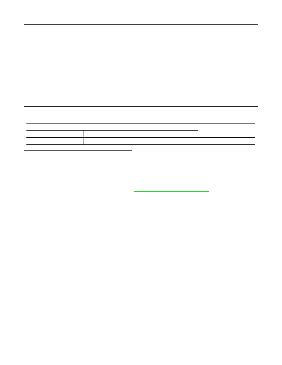
BCM harness connector
Resistance (
Ω
)
Connector No.
Terminal No.
M122
91
90
Approx. 54 – 66
LAN
DLC BRANCH LINE CIRCUIT
LAN-135
< DTC/CIRCUIT DIAGNOSIS >
[CAN SYSTEM (TYPE 5)]
C
D
E
F
G
H
I
J
K
L
B
A
O
P
N
DLC BRANCH LINE CIRCUIT
Diagnosis Procedure
INFOID:0000000005595437
1.
CHECK CONNECTOR
1.
Turn the ignition switch OFF.
2.
Disconnect the battery cable from the negative terminal.
3.
Check the terminals and connectors of the data link connector for damage, bend and loose connection
(connector side and harness side).
Is the inspection result normal?
YES
>> GO TO 2.
NO
>> Repair the terminal and connector.
2.
CHECK HARNESS FOR OPEN CIRCUIT
Check the resistance between the data link connector terminals.
Is the measurement value within the specification?
YES (Present error)>>Check CAN system type decision again.
YES (Past error)>>Error was detected in the data link connector branch line circuit.
NO
>> Repair the data link connector branch line.
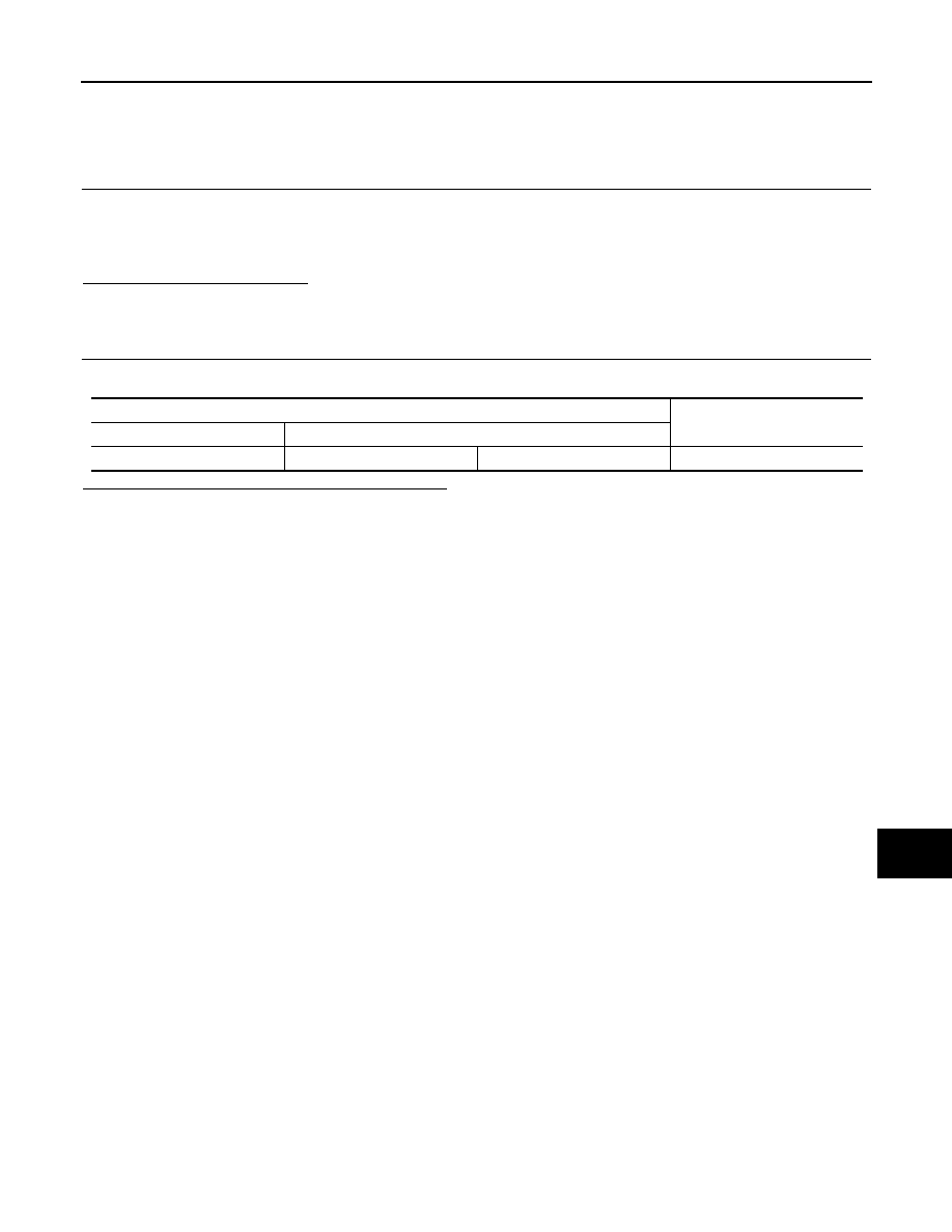
Data link connector
Resistance (
Ω
)
Connector No.
Terminal No.
M4
6
14
Approx. 54 – 66
LAN-136
< DTC/CIRCUIT DIAGNOSIS >
[CAN SYSTEM (TYPE 5)]
STRG BRANCH LINE CIRCUIT
STRG BRANCH LINE CIRCUIT
Diagnosis Procedure
INFOID:0000000005595438
1.
CHECK CONNECTOR
1.
Turn the ignition switch OFF.
2.
Disconnect the battery cable from the negative terminal.
3.
Check the terminals and connectors of the steering angle sensor for damage, bend and loose connection
(unit side and connector side).
Is the inspection result normal?
YES
>> GO TO 2.
NO
>> Repair the terminal and connector.
2.
CHECK HARNESS FOR OPEN CIRCUIT
1.
Disconnect the connector of steering angle sensor.
2.
Check the resistance between the steering angle sensor harness connector terminals.
Is the measurement value within the specification?
YES
>> GO TO 3.
NO
>> Repair the steering angle sensor branch line.
3.
CHECK POWER SUPPLY AND GROUND CIRCUIT
Check the power supply and the ground circuit of the steering angle sensor. Refer to
Is the inspection result normal?
YES (Present error)>>Replace the steering angle sensor. Refer to
BRC-116, "Removal and Installation"
.
YES (Past error)>>Error was detected in the steering angle sensor branch line.
NO
>> Repair the power supply and the ground circuit.
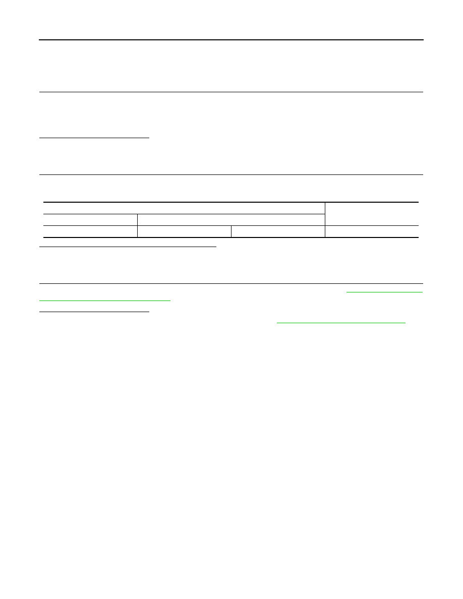
Steering angle sensor harness connector
Resistance (
Ω
)
Connector No.
Terminal No.
M30
5
2
Approx. 54 – 66
LAN
ABS BRANCH LINE CIRCUIT
LAN-137
< DTC/CIRCUIT DIAGNOSIS >
[CAN SYSTEM (TYPE 5)]
C
D
E
F
G
H
I
J
K
L
B
A
O
P
N
ABS BRANCH LINE CIRCUIT
Diagnosis Procedure
INFOID:0000000005595439
1.
CHECK CONNECTOR
1.
Turn the ignition switch OFF.
2.
Disconnect the battery cable from the negative terminal.
3.
Check the terminals and connectors of the ABS actuator and electric unit (control unit) for damage, bend
and loose connection (unit side and connector side).
Is the inspection result normal?
YES
>> GO TO 2.
NO
>> Repair the terminal and connector.
2.
CHECK HARNESS FOR OPEN CIRCUIT
1.
Disconnect the connector of ABS actuator and electric unit (control unit).
2.
Check the resistance between the ABS actuator and electric unit (control unit) harness connector termi-
nals.
Is the measurement value within the specification?
YES
>> GO TO 3.
NO
>> Repair the ABS actuator and electric unit (control unit) branch line.
3.
CHECK POWER SUPPLY AND GROUND CIRCUIT
Check the power supply and the ground circuit of the ABS actuator and electric unit (control unit). Refer to
Is the inspection result normal?
YES (Present error)>>Replace the ABS actuator and electric unit (control unit). Refer to
.
YES (Past error)>>Error was detected in the ABS actuator and electric unit (control unit) branch line.
NO
>> Repair the power supply and the ground circuit.
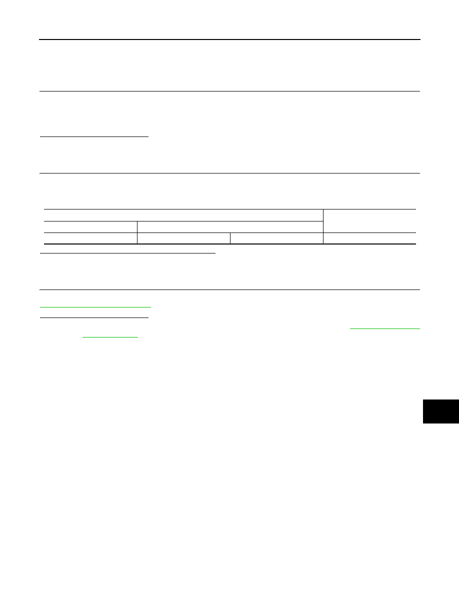
ABS actuator and electric unit (control unit) harness connector
Resistance (
Ω
)
Connector No.
Terminal No.
E36
23
21
Approx. 54 – 66
Нет комментариевНе стесняйтесь поделиться с нами вашим ценным мнением.
Текст