Nissan Murano Z51. Instruction — part 280

BCS
BCM (BODY CONTROL MODULE)
BCS-87
< ECU DIAGNOSIS INFORMATION >
C
D
E
F
G
H
I
J
K
L
B
A
O
P
N
Display contents of CONSULT
Fail-safe
Cancellation
B2013: ID DISCORD BCM-S/L
Inhibit engine cranking
Erase DTC
B2014: CHAIN OF S/L-BCM
Inhibit engine cranking
Erase DTC
B2190: NATS ANTENNA AMP
Inhibit engine cranking
Erase DTC
B2191: DIFFERENCE OF KEY
Inhibit engine cranking
Erase DTC
B2192: ID DISCORD BCM-ECM
Inhibit engine cranking
Erase DTC
B2193: CHAIN OF BCM-ECM
Inhibit engine cranking
Erase DTC
B2195: ANTI SCANNING
Inhibit engine cranking
Ignition switch ON
→
OFF
B2557: VEHICLE SPEED
Inhibit steering lock
When normal vehicle speed signals are received from ABS actua-
tor and electric unit (control unit) for 500 ms
B2560: STARTER CONT RELAY
Inhibit engine cranking
500 ms after the following CAN signal communication status be-
comes consistent
• Starter control relay signal
• Starter relay status signal
B2601: SHIFT POSITION
Inhibit steering lock
500 ms after the following signal reception status becomes consis-
tent
• Selector lever P position switch signal
• P range signal (CAN)
B2602: SHIFT POSITION
Inhibit steering lock
5 seconds after the following BCM recognition conditions are ful-
filled
• Ignition switch is in the ON position
• Selector lever P position switch signal: Except P position (battery
voltage)
• Vehicle speed: 4 km/h (2.5 MPH) or more
B2603: SHIFT POSI STATUS
Inhibit steering lock
500 ms after the following BCM recognition conditions are fulfilled
• Ignition switch is in the ON position
• Selector lever P position switch signal: Except P position (battery
voltage)
• Selector lever P/N position signal: Except P and N positions (0 V)
B2604: PNP SW
Inhibit steering lock
500 ms after any of the following BCM recognition conditions are
fulfilled
• Status 1
- Ignition switch is in the ON position
- Selector lever P/N position signal: P and N position (battery volt-
age)
- P range signal or N range signal (CAN): ON
• Status 2
- Ignition switch is in the ON position
- Selector lever P/N position signal: Except P and N positions (0 V)
- P range signal and N range signal (CAN): OFF
B2605: PNP SW
Inhibit steering lock
500 ms after any of the following BCM recognition conditions are
fulfilled
• Ignition switch is in the ON position
- Power position: IGN
- Selector lever P/N position signal: Except P and N positions (0 V)
- Interlock/PNP switch signal (CAN): OFF
• Status 2
- Ignition switch is in the ON position
- Selector lever P/N position signal: P or N position (battery volt-
age)
- PNP switch signal (CAN): ON
B2606: S/L RELAY
Inhibit engine cranking
500 ms after the following CAN signal communication status be-
comes consistent
• Steering lock relay signal (Request signal)
• Steering lock relay signal (Condition signal)

BCS-88
< ECU DIAGNOSIS INFORMATION >
BCM (BODY CONTROL MODULE)
HIGH FLASHER OPERATION
BCM detects the turn signal lamp circuit status by the current value.
BCM increases the turn signal lamp blinking speed if the bulb or harness open is detected with the turn signal
lamp operating.
NOTE:
The blinking speed is normal while activating the hazard warning lamp.
FAIL-SAFE CONTROL BY RAIN SENSOR MALFUNCTION
• BCM judges the rain sensor serial link error by the rain sensor serial link condition and detects the rain sen-
sor malfunction by rain sensor malfunction signal.
• When BCM detects the rain sensor serial link error or the rain sensor malfunction while front wiper AUTO
operation, BCM operates a fail-safe control.
NOTE:
If rain sensor malfunction is detected when ignition switch is turned OFF
⇒
ON and front wiper switch is INT/
AUTO position, BCM operates a fail-safe control.
REAR WIPER MOTOR PROTECTION
BCM detects the rear wiper stopping position according to the rear wiper stop position signal.
When the rear wiper stop position signal does not change for more than 5 seconds while driving the rear
wiper, BCM stops power supply to protect the rear wiper motor.
Condition of cancellation
1.
More than 1 minute is passed after the rear wiper stop.
B2607: S/L RELAY
Inhibit engine cranking
500 ms after the following CAN signal communication status be-
comes consistent
• Steering lock relay signal (Request signal)
• Steering lock relay signal (Condition signal)
B2608: STARTER RELAY
Inhibit engine cranking
500 ms after the following signal communication status becomes
consistent
• Starter motor relay control signal
• Starter relay status signal (CAN)
B2609: S/L STATUS
• Inhibit engine cranking
• Inhibit steering lock
When the following steering lock conditions agree
• BCM steering lock control status
• Steering lock condition No. 1 signal status
• Steering lock condition No. 2 signal status
B260A: IGNITION RELAY
Inhibit engine cranking
500 ms after the following conditions are fulfilled
• IGN relay (IPDM E/R) control signal: OFF (Battery voltage)
• Ignition ON signal (CAN to IPDM E/R): OFF (Request signal)
• Ignition ON signal (CAN from IPDM E/R): OFF (Condition signal)
B260F: ENG STATE SIG LOST
Maintains the power supply
position attained at the time
of DTC detection
When any of the following conditions are fulfilled
• Power position changes to ACC
• Receives engine status signal (CAN)
B2612: S/L STATUS
• Inhibit engine cranking
• Inhibit steering lock
When any of the following conditions are fulfilled
• Steering lock unit status signal (CAN) is received normally
• The BCM steering lock control status matches the steering lock
status recognized by the steering lock unit status signal (CAN
from IPDM E/R)
B2617: STARTER RELAY CIRC
Inhibit engine cranking
1 second after the starter motor relay control inside BCM becomes
normal
B2618: BCM
Inhibit engine cranking
1 second after the ignition relay (IPDM E/R) control inside BCM be-
comes normal
B2619: BCM
Inhibit engine cranking
1 second after the steering lock unit power supply output control in-
side BCM becomes normal
B261E: VEHICLE TYPE
Inhibit engine cranking
BCM initialization
B26E9: S/L STATUS
• Inhibit engine cranking
• Inhibit steering lock
When BCM transmits the LOCK request signal to steering lock unit,
and receives LOCK response signal from steering lock unit, the fol-
lowing conditions are fulfilled
• Steering condition No. 1 signal: LOCK (0V)
• Steering condition No. 2 signal: LOCK (Battery voltage)
Display contents of CONSULT
Fail-safe
Cancellation

BCS
BCM (BODY CONTROL MODULE)
BCS-89
< ECU DIAGNOSIS INFORMATION >
C
D
E
F
G
H
I
J
K
L
B
A
O
P
N
2.
Turn rear wiper switch OFF.
3.
Operate the rear wiper switch or rear washer switch.
DTC Inspection Priority Chart
INFOID:0000000005518311
If some DTCs are displayed at the same time, perform inspections one by one based on the following priority
chart.
Priority
DTC
1
B2562: LOW VOLTAGE
2
• U1000: CAN COMM
• U1010: CONTROL UNIT(CAN)
3
• B2190: NATS ANTENNA AMP
• B2191: DIFFERENCE OF KEY
• B2192: ID DISCORD BCM-ECM
• B2193: CHAIN OF BCM-ECM
• B2195: ANTI SCANNING
4
• B2013: ID DISCORD BCM-S/L
• B2014: CHAIN OF S/L-BCM
• B2553: IGNITION RELAY
• B2555: STOP LAMP
• B2556: PUSH-BTN IGN SW
• B2557: VEHICLE SPEED
• B2560: STARTER CONT RELAY
• B2601: SHIFT POSITION
• B2602: SHIFT POSITION
• B2603: SHIFT POSI STATUS
• B2604: PNP SW
• B2605: PNP SW
• B2606: S/L RELAY
• B2607: S/L RELAY
• B2608: STARTER RELAY
• B2609: S/L STATUS
• B260A: IGNITION RELAY
• B260B: STEERING LOCK UNIT
• B260C: STEERING LOCK UNIT
• B260D: STEERING LOCK UNIT
• B260F: ENG STATE SIG LOST
• B2612: S/L STATUS
• B2614: ACC RELAY CIRC
• B2615: BLOWER RELAY CIRC
• B2616: IGN RELAY CIRC
• B2617: STARTER RELAY CIRC
• B2618: BCM
• B2619: BCM
• B261A: PUSH-BTN IGN SW
• B261E: VEHICLE TYPE
• B26E9: S/L STATUS
• B26EA: KEY REGISTRATION
• C1729: VHCL SPEED SIG ERR
• U0415: VEHICLE SPEED SIG
BCS-90
< ECU DIAGNOSIS INFORMATION >
BCM (BODY CONTROL MODULE)
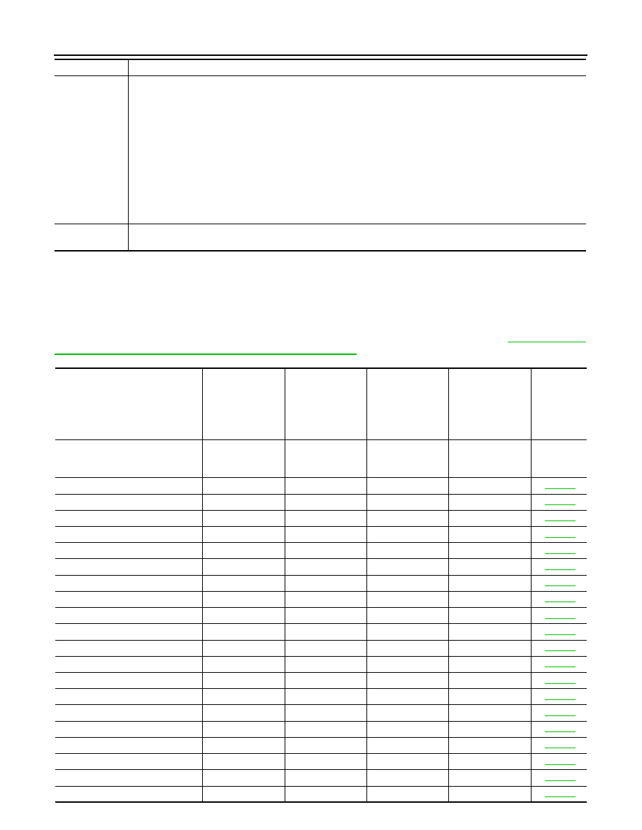
DTC Index
INFOID:0000000005518312
NOTE:
The details of time display are as follows.
• CRNT: A malfunction is detected now.
• PAST: A malfunction was detected in the past.
IGN counter is displayed on Freeze Frame Data. For details of Freeze Frame Data, refer to
MON ITEM : CONSULT-III Function (BCM - COMMON ITEM)"
.
5
• C1704: LOW PRESSURE FL
• C1705: LOW PRESSURE FR
• C1706: LOW PRESSURE RR
• C1707: LOW PRESSURE RL
• C1708: [NO DATA] FL
• C1709: [NO DATA] FR
• C1710: [NO DATA] RR
• C1711: [NO DATA] RL
• C1716: [PRESSDATA ERR] FL
• C1717: [PRESSDATA ERR] FR
• C1718: [PRESSDATA ERR] RR
• C1719: [PRESSDATA ERR] RL
• C1734: CONTROL UNIT
6
• B2622: INSIDE ANTENNA
• B2623: INSIDE ANTENNA
Priority
DTC
CONSULT display
Fail-safe
Freeze Frame
Data
•Vehicle Speed
•Odo/Trip Meter
•Vehicle Condi-
tion
Intelligent Key
warning lamp ON
Tire pressure
monitor warning
lamp ON
Reference
page
No DTC is detected.
further testing
may be required.
—
—
—
—
—
U1000: CAN COMM
—
—
—
—
U1010: CONTROL UNIT(CAN)
—
—
—
—
U0415: VEHICLE SPEED SIG
—
—
—
—
B2013: ID DISCORD BCM-S/L*
×
×
—
—
B2014: CHAIN OF S/L-BCM*
×
×
—
—
B2190: NATS ANTENNA AMP
×
—
—
—
B2191: DIFFERENCE OF KEY
×
—
—
—
B2192: ID DISCORD BCM-ECM
×
—
—
—
B2193: CHAIN OF BCM-ECM
×
—
—
—
B2195: ANTI SCANNING
×
—
—
—
B2553: IGNITION RELAY
—
×
—
—
B2555: STOP LAMP
—
×
—
—
B2556: PUSH-BTN IGN SW
—
×
×
—
B2557: VEHICLE SPEED
×
×
×
—
B2560: STARTER CONT RELAY
×
×
×
—
B2562: LOW VOLTAGE
—
×
—
—
B2601: SHIFT POSITION
×
×
×
—
B2602: SHIFT POSITION
×
×
×
—
B2603: SHIFT POSI STATUS
×
×
×
—
B2604: PNP SW
×
×
×
—
Нет комментариевНе стесняйтесь поделиться с нами вашим ценным мнением.
Текст