Nissan Murano Z51. Instruction — part 84

AV
RGB (R: RED) SIGNAL CIRCUIT (AV CONTROL UNIT TO FRONT DISPLAY
UNIT)
AV-115
< DTC/CIRCUIT DIAGNOSIS >
[BOSE AUDIO WITHOUT NAVIGATION]
C
D
E
F
G
H
I
J
K
L
M
B
A
O
P
RGB (R: RED) SIGNAL CIRCUIT (AV CONTROL UNIT TO FRONT DISPLAY
UNIT)
Description
INFOID:0000000005528516
Transmit the image displayed with AV control unit with RGB image signal to the front display unit.
Diagnosis Procedure
INFOID:0000000005528517
1.
CHECK CONTINUITY RGB (R: RED) SIGNAL CIRCUIT
1.
Turn ignition switch OFF.
2.
Disconnect front display unit connector and AV control unit connector.
3.
Check continuity between front display unit harness connector and AV control unit harness connector.
4.
Check continuity between front display unit harness connector and ground.
Is the inspection result normal?
YES
>> GO TO 2.
NO
>> Repair harness or connector.
2.
CHECK RGB (R: RED) SIGNAL
1.
Connect front display unit connector and AV control unit connector.
2.
Turn ignition switch ON.
3.
Check signal between front display unit harness connector and ground using an oscilloscope.
Is the inspection result normal?
YES
>> Replace front display unit.
NO
>> Replace AV control unit.
Front display unit
AV control unit
Continuity
Connector
Terminal
Connector
Terminal
M49
17
M129
40
Existed
Front display unit
Ground
Continuity
Connector
Terminal
M49
17
Not existed
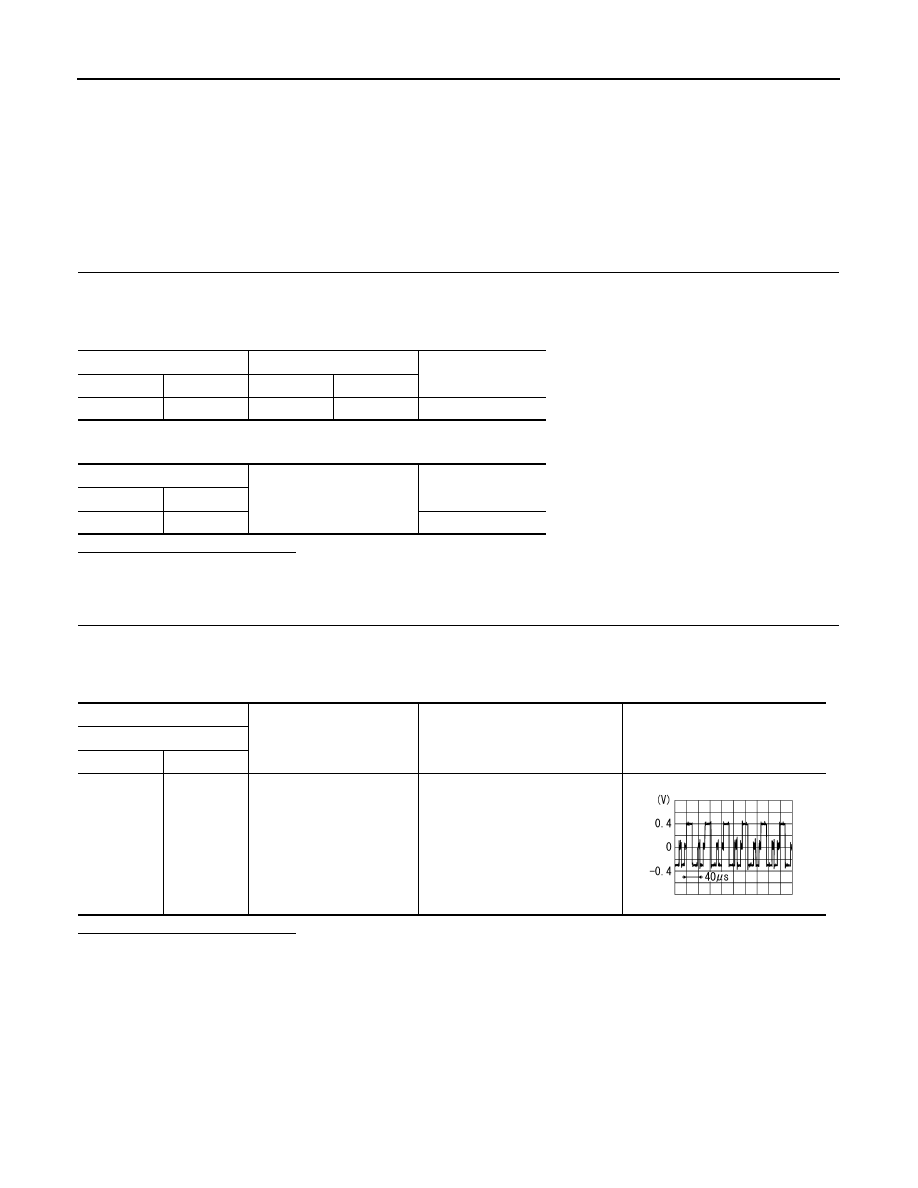
(+)
(
−
)
Condition
Signal
Front display unit
Connector
Terminal
M49
17
Ground
Start confirmation/adjustment
mode, and then display color bar
by selecting “Color Spectrum Bar”
on DISPLAY DIAGNOSIS screen.
SKIB2238J
AV-116
< DTC/CIRCUIT DIAGNOSIS >
[BOSE AUDIO WITHOUT NAVIGATION]
RGB (G: GREEN) SIGNAL CIRCUIT (AV CONTROL UNIT TO FRONT DISPLAY
UNIT)
RGB (G: GREEN) SIGNAL CIRCUIT (AV CONTROL UNIT TO FRONT DIS-
PLAY UNIT)
Description
INFOID:0000000005528518
Transmit the image displayed with AV control unit with RGB image signal to the front display unit.
Diagnosis Procedure
INFOID:0000000005528519
1.
CHECK CONTINUITY RGB (G: GREEN) SIGNAL CIRCUIT
1.
Turn ignition switch OFF.
2.
Disconnect front display unit connector and AV control unit connector.
3.
Check continuity between front display unit harness connector and AV control unit harness connector.
4.
Check continuity between front display unit harness connector and ground.
Is the inspection result normal?
YES
>> GO TO 2.
NO
>> Repair harness or connector.
2.
CHECK RGB (G: GREEN) SIGNAL
1.
Connect front display unit connector and AV control unit connector.
2.
Turn ignition switch ON.
3.
Check signal between front display unit harness connector and ground using an oscilloscope.
Is the inspection result normal?
YES
>> Replace front display unit.
NO
>> Replace AV control unit.
Front display unit
AV control unit
Continuity
Connector
Terminal
Connector
Terminal
M49
6
M129
39
Existed
Front display unit
Ground
Continuity
Connector
Terminal
M49
6
Not existed
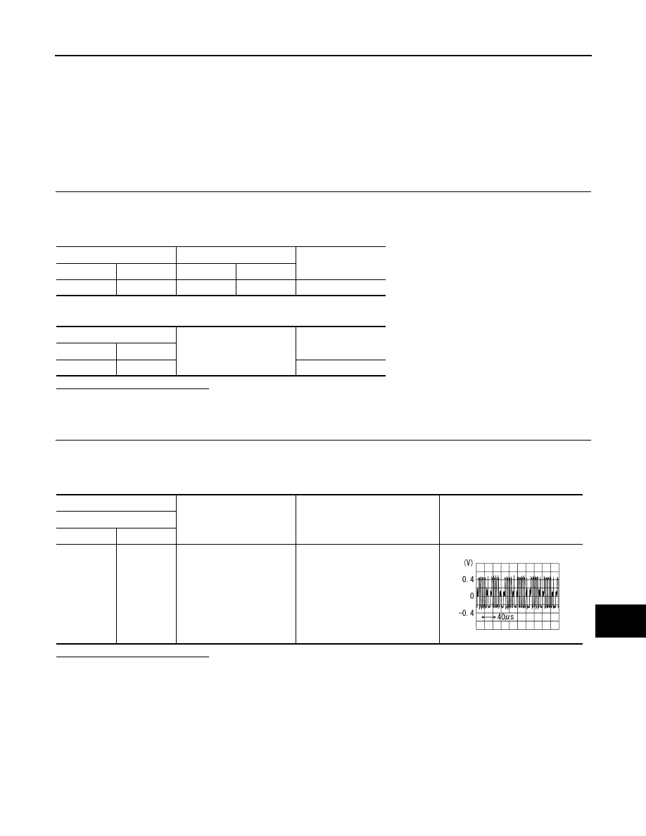
(+)
(
−
)
Condition
Signal
Front display unit
Connector
Terminal
M49
6
Ground
Start confirmation/adjustment
mode, and then display color bar
by selecting “Color Spectrum Bar”
on DISPLAY DIAGNOSIS screen.
SKIB2236J
AV
RGB (B: BLUE) SIGNAL CIRCUIT (AV CONTROL UNIT TO FRONT DISPLAY
UNIT)
AV-117
< DTC/CIRCUIT DIAGNOSIS >
[BOSE AUDIO WITHOUT NAVIGATION]
C
D
E
F
G
H
I
J
K
L
M
B
A
O
P
RGB (B: BLUE) SIGNAL CIRCUIT (AV CONTROL UNIT TO FRONT DIS-
PLAY UNIT)
Description
INFOID:0000000005528520
Transmit the image displayed with AV control unit with RGB image signal to the front display unit.
Diagnosis Procedure
INFOID:0000000005528521
1.
CHECK CONTINUITY RGB (B: BLUE) SIGNAL CIRCUIT
1.
Turn ignition switch OFF.
2.
Disconnect front display unit connector and AV control unit connector.
3.
Check continuity between front display unit harness connector and AV control unit harness connector.
4.
Check continuity between front display unit harness connector and ground.
Is the inspection result normal?
YES
>> GO TO 2.
NO
>> Repair harness or connector.
2.
CHECK RGB (B: BLUE) SIGNAL
1.
Connect front display unit connector and AV control unit connector.
2.
Turn ignition switch ON.
3.
Check signal between front display unit harness connector and ground using an oscilloscope.
Is the inspection result normal?
YES
>> Replace front display unit.
NO
>> Replace AV control unit.
Front display unit
AV control unit
Continuity
Connector
Terminal
Connector
Terminal
M49
18
M129
38
Existed
Front display unit
Ground
Continuity
Connector
Terminal
M49
18
Not existed
(+)
(
−
)
Condition
Signal
Front display unit
Connector
Terminal
M49
18
Ground
Start confirmation/adjustment
mode, and then display color bar
by selecting “Color Spectrum Bar”
on DISPLAY DIAGNOSIS screen.
SKIB2237J
AV-118
< DTC/CIRCUIT DIAGNOSIS >
[BOSE AUDIO WITHOUT NAVIGATION]
RGB SYNCHRONIZING SIGNAL CIRCUIT
RGB SYNCHRONIZING SIGNAL CIRCUIT
Description
INFOID:0000000005528522
Transmit the RGB synchronizing signal to the front display unit so as to synchronize the RGB image displayed
with AV control unit.
Diagnosis Procedure
INFOID:0000000005528523
1.
CHECK CONTINUITY RGB SYNCHRONIZING SIGNAL CIRCUIT
1.
Turn ignition switch OFF.
2.
Disconnect front display unit connector and AV control unit connector.
3.
Check continuity between front display unit harness connector and AV control unit harness connector.
4.
Check continuity between front display unit harness connector and ground.
Is the inspection result normal?
YES
>> GO TO 2.
NO
>> Repair harness or connector.
2.
CHECK RGB SYNCHRONIZING SIGNAL
1.
Connect front display unit connector and AV control unit connector.
2.
Turn ignition switch ON.
3.
Check signal between front display unit harness connector and ground using an oscilloscope.
Is the inspection result normal?
YES
>> Replace front display unit.
NO
>> Replace AV control unit.
Front display unit
AV control unit
Continuity
Connector
Terminal
Connector
Terminal
M49
19
M129
41
Existed
Front display unit
Ground
Continuity
Connector
Terminal
M49
19
Not existed
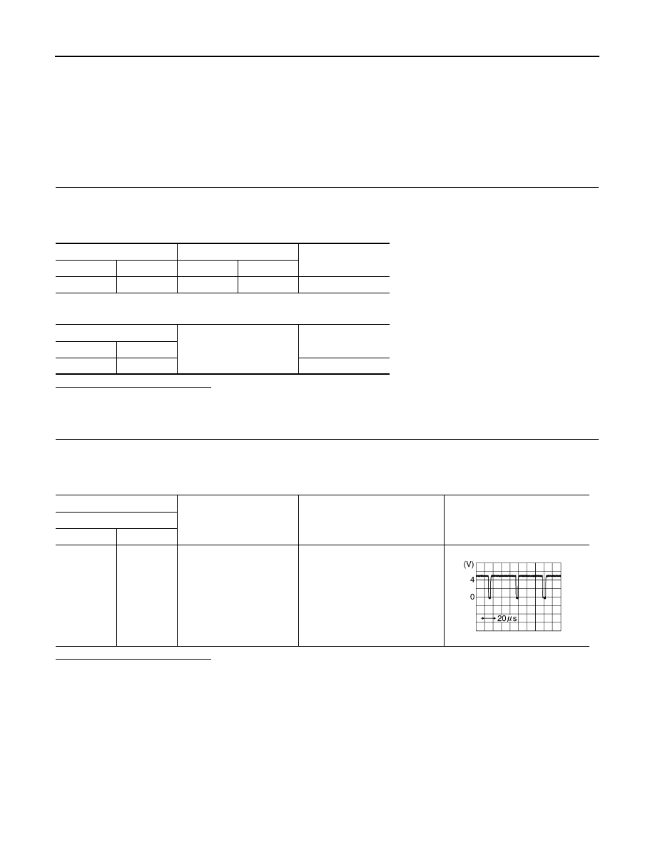
(+)
(
−
)
Condition
Signal
Front display unit
Connector
Terminal
M49
19
Ground
—
SKIB3603E
Нет комментариевНе стесняйтесь поделиться с нами вашим ценным мнением.
Текст