Nissan Murano Z51. Instruction — part 905
INTERIOR ROOM LAMP CONTROL CIRCUIT
INL-21
< DTC/CIRCUIT DIAGNOSIS >
C
D
E
F
G
H
I
J
K
M
A
B
INL
N
O
P
INTERIOR ROOM LAMP CONTROL CIRCUIT
Description
INFOID:0000000005516774
Controls each interior room lamp (ground side) by PWM signal.
NOTE:
PWM signal control period is approximately 250 Hz (in the gradual brightening/dimming).
Component Function Check
INFOID:0000000005516775
CAUTION:
Before performing the diagnosis, check that the following is normal.
• Interior room lamp power supply
• Map lamp bulb
• Personal lamp bulb
1.
CHECK INTERIOR ROOM LAMP CONTROL FUNCTION
CONSULT-III ACTIVE TEST
1.
Switch the map lamp switch to DOOR.
2.
Turn the ignition switch ON.
3.
Select “INT LAMP” of BCM (INT LAMP) active test item.
4.
With operating the test items, check that each interior room lamp turns ON/OFF (gradual brightening/dim-
ming).
Does the interior room lamp turns ON/OFF (gradual brightening/dimming)?
YES
>> Interior room lamp control circuit is normal.
NO
>> Refer to
.
Diagnosis Procedure
INFOID:0000000005516776
1.
CHECK INTERIOR ROOM LAMP CONTROL OUTPUT
CONSULT-III ACTIVE TEST
1.
Turn ignition switch OFF.
2.
Remove all the bulbs of map lamp and personal lamp.
3.
Select “INT LAMP” of BCM (INT LAMP) active test item.
4.
With operating the test item, check continuity between BCM harness connector and ground.
Is the measurement value normal?
YES
>> GO TO 2.
Fixed ON>>GO TO 3.
Fixed OFF>>Replace BCM.
2.
CHECK INTERIOR ROOM LAMP CONTROL OPEN CIRCUIT
1.
Turn ignition switch OFF.
2.
Disconnect BCM connector, map lamp connector and personal lamp connector.
3.
Check continuity between BCM harness connector, map lamp harness connector and personal lamp har-
ness connector.
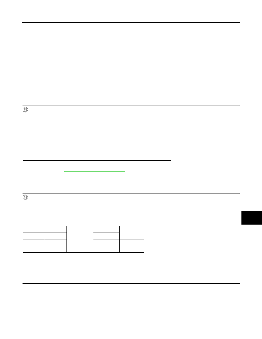
On
: Interior room lamp gradual brightening
Off
: Interior room lamp gradual dimming
BCM
Ground
Test item
Continuity
Connector
Terminal
INT LAMP
M119
19
On
Existed
Off
Not existed
INL-22
< DTC/CIRCUIT DIAGNOSIS >
INTERIOR ROOM LAMP CONTROL CIRCUIT
Does continuity exist?
YES
>> Replace the map lamp or the personal lamp.
NO
>> Repair the harnesses or connectors.
3.
CHECK INTERIOR ROOM LAMP CONTROL SHORT CIRCUIT
1.
Turn ignition switch OFF.
2.
Disconnect BCM connector, map lamp connector and personal lamp connector.
3.
Check continuity between BCM harness connector and ground.
Does continuity exist?
YES
>> Repair the harnesses or connectors.
NO
>> Replace BCM.
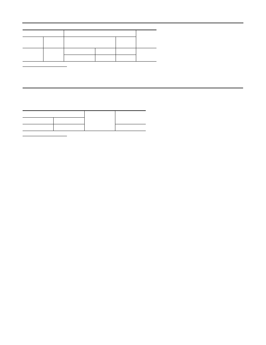
BCM
Map lamp/personal lamp
Continuity
Connec-
tor
Terminal
Connector
Terminal
M119
19
Map lamp
R19
2
Existed
Personal lamp
R21
3
BCM
Ground
Continuity
Connector
Terminal
M119
19
Not existed
STEP LAMP CIRCUIT
INL-23
< DTC/CIRCUIT DIAGNOSIS >
C
D
E
F
G
H
I
J
K
M
A
B
INL
N
O
P
STEP LAMP CIRCUIT
Description
INFOID:0000000005516777
Controls the step lamp (ground side) to turn the step lamp ON and OFF.
Component Function Check
INFOID:0000000005516778
CAUTION:
Before performing the diagnosis, check that the following is normal.
• Interior room lamp power supply
• Step lamp bulb
1.
CHECK STEP LAMP OPERATION
CONSULT-III ACTIVE TEST
1.
Turn the ignition switch ON.
2.
Select "STEP LAMP TEST" of BCM (INT LAMP) active test item.
3.
With operating the test items, check that step lamp turns ON/OFF.
Does the step lamp turn ON/OFF?
YES
>> Step lamp circuit is normal.
NO
>> Refer to
.
Diagnosis Procedure
INFOID:0000000005516779
1.
CHECK STEP LAMP OUTPUT
CONSULT-III ACTIVE TEST
1.
Turn the ignition switch OFF.
2.
Remove the step lamp bulbs (driver side and passenger side).
3.
Turn the ignition switch ON.
4.
Select “STEP LAMP TEST” of BCM (INT LAMP) active test item.
5.
With operating the test item, check continuity between BCM harness connector and the ground.
Is the measurement value normal?
YES
>> GO TO 2.
Fixed ON>>GO TO 3.
Fixed OFF>>Replace BCM.
2.
CHECK STEP LAMP OPEN CIRCUIT
1.
Turn the ignition switch OFF.
2.
Disconnect BCM connector, and step lamp connector.
3.
Check continuity between BCM harness connector and step lamp harness connector.
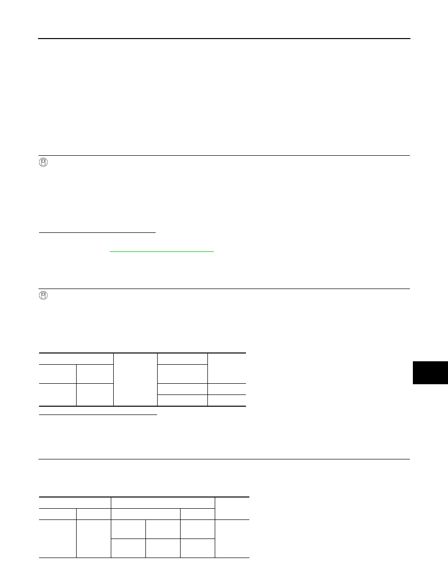
On
: Step lamp ON
Off
: Step lamp OFF
BCM
Ground
Test item
Continuity
Connector
Terminal
STEP LAMP
TEST
M119
7
On
Existed
Off
Not existed
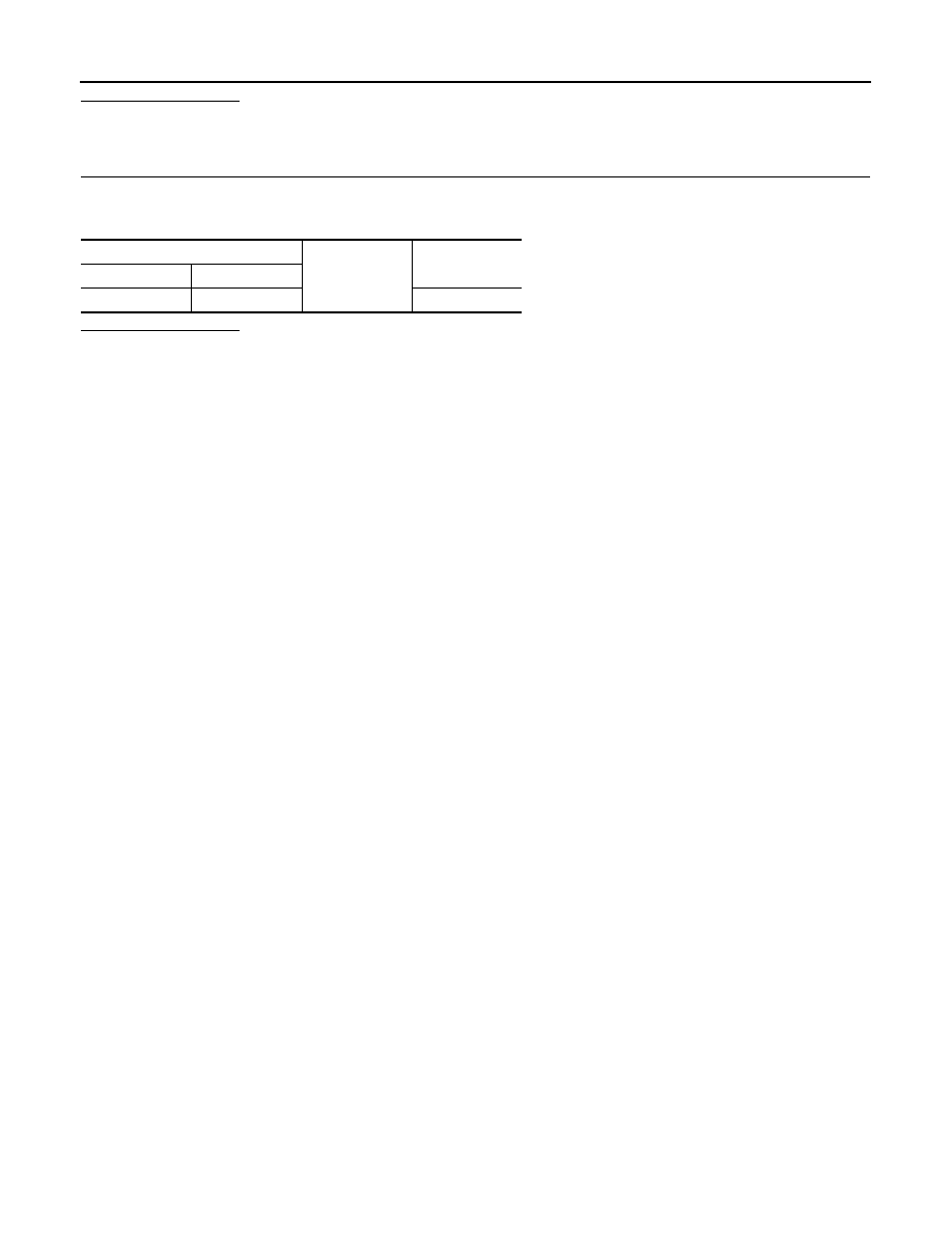
BCM
Step lamp
Continuity
Connector
Terminal
Connector
Terminal
M119
7
Driver
side
D17
2
Existed
Passen-
ger side
D51
2
INL-24
< DTC/CIRCUIT DIAGNOSIS >
STEP LAMP CIRCUIT
Does continuity exist?
YES
>> Replace step lamp.
NO
>> Repair harnesses or connectors.
3.
CHECK STEP LAMP SHORT CIRCUIT
1.
Turn the ignition switch OFF.
2.
Check continuity between BCM harness connector and the ground.
Does continuity exist?
YES
>> Repair the harnesses or connectors.
NO
>> Replace BCM.
BCM
Ground
Continuity
Connector
Terminal
M119
7
Not existed
Нет комментариевНе стесняйтесь поделиться с нами вашим ценным мнением.
Текст