Nissan Murano Z51. Instruction — part 1457
SERVICE DATA AND SPECIFICATIONS (SDS)
TM-179
< SERVICE DATA AND SPECIFICATIONS (SDS)
[CVT: RE0F09B]
C
E
F
G
H
I
J
K
L
M
A
B
TM
N
O
P
SERVICE DATA AND SPECIFICATIONS (SDS)
SERVICE DATA AND SPECIFICATIONS (SDS)
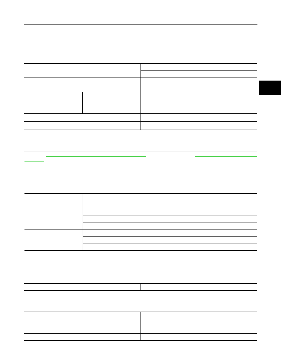
General Specification
INFOID:0000000005514133
*1: Refer to
MA-15, "FOR NORTH AMERICA : Fluids and Lubricants"
(FOR NORTH AMERICA),
MA-16, "FOR MEXICO : Fluids and
(FOR MEXICO).
*2: The fluid capacity is the reference value. Check the fluid level with CVT fluid level gauge.
Vehicle Speed When Shifting Gears
INFOID:0000000005514134
Numerical value data are reference values.
Unit: rpm
CAUTION:
Lock-up clutch is engaged when vehicle speed is approximately 18 km/h (11 MPH) to 90 km/h (56 MPH).
Stall Speed
INFOID:0000000005514135
Line Pressure
INFOID:0000000005514136
Unit: kPa (kg/cm
2
, psi)
Applied model
VQ35DE engine
2WD
AWD
CVT model
RE0F09B
CVT assembly model code number
1XE1B
1XE1C
Transmission gear ratio
D range
Variable
Reverse
1.766
Final drive
5.173
Recommended fluid
Genuine NISSAN CVT Fluid NS-2
*1
Fluid capacity liter (US qt, Imp qt)
10.2 (10-6/8, 9)
*2
CAUTION:
• Use only Genuine NISSAN CVT Fluid NS-2. Never mix with other fluid.
• Using CVT fluid other than Genuine NISSAN CVT Fluid NS-2 will deteriorate in driveability and CVT durability, and may dam-
age the CVT, which is not covered by the NISSAN new vehicle limited warranty.
Throttle position
Shift pattern
Engine speed
At 40 km/h (25 MPH)
At 60 km/h (37 MPH)
8/8
“D” position
2,600 – 4,100
3,600 – 5,300
Overdrive OFF condition
2,600 – 4,100
3,600 – 5,300
“L” position
2,600 – 4,100
3,600 – 5,300
2/8
“D” position
1,000 – 3,000
1,100 – 3,400
Overdrive OFF condition
2,200 – 3,000
2,800 – 3,600
“L” position
2,600 – 3,500
3,600 – 4,500
Stall speed
2,700 – 3,500 rpm
Engine speed
Line pressure
“R”, “D” and “L” positions
At idle
700 (7.14, 101.5)
At stall
5,700 (58.14, 826.5)
TM-180
< SERVICE DATA AND SPECIFICATIONS (SDS)
[CVT: RE0F09B]
SERVICE DATA AND SPECIFICATIONS (SDS)
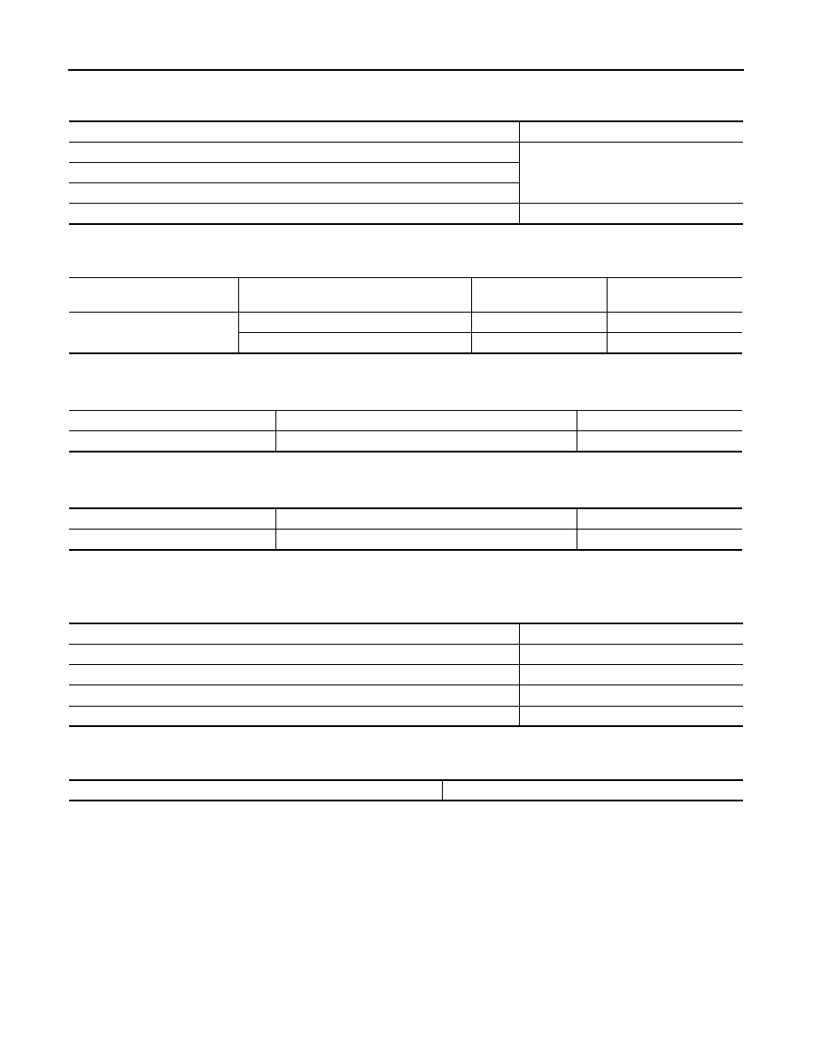
Solenoid Valves
INFOID:0000000005514137
CVT Fluid Temperature Sensor
INFOID:0000000005514138
Primary Speed Sensor
INFOID:0000000005514139
Secondary Speed Sensor
INFOID:0000000005514140
Step Motor
INFOID:0000000005514141
Torque Converter
INFOID:0000000005514142
Name
Resistance (Approx.)
Pressure control solenoid valve B (secondary pressure solenoid valve)
3.0 – 9.0
Ω
Pressure control solenoid valve A (line pressure solenoid valve)
Torque converter clutch solenoid valve
Lock-up select solenoid valve
6.0 – 19.0
Ω
Name
Condition
CONSULT-III “Data Mon-
itor” (Approx.)
Resistance (Approx.)
CVT fluid temperature sensor
When CVT fluid temperature is 20
°
C (68
°
F)
1.9 – 2.2 V
6.5 k
Ω
When CVT fluid temperature is 80
°
C (176
°
F)
0.8 – 1.1 V
0.9 k
Ω
Name
Condition
Data (Approx.)
Primary speed sensor
When driving [“L” position, 20 km/h (12 MPH)]
680 Hz
Name
Condition
Data (Approx.)
Secondary speed sensor
When driving [“D” position, 20 km/h (12 MPH)]
350 Hz
Name
Resistance (Approx.)
Step motor A
15.0
Ω
Step motor B
15.0
Ω
Step motor C
15.0
Ω
Step motor D
15.0
Ω
Dimension between end of converter housing and torque converter
14.0 mm (0.55 in)
VTL-1
VENTILATION, HEATER & AIR CONDITIONER
C
D
E
F
G
H
J
K
L
M
SECTION
VTL
A
B
VTL
N
O
P
CONTENTS
VENTILATION SYSTEM
WITHOUT 7 INCH DISPLAY
SYSTEM DESCRIPTION . . . . . . . ..
SWITCHES AND THEIR CONTROL FUNC-
TION . . . . . . . . . . . . . . . . .
System Description . . . . . . . . . . . . ...
AIR DISTRIBUTION . . . . . . . . . . .
System Description . . . . . . . . . . . . ...
PRECAUTION . . . . . . . . . . . ...
PRECAUTIONS . . . . . . . . . . . . ...
FOR USA AND CANADA . . . . . . . . . . ....
FOR MEXICO . . . . . . . . . . . . . . . ..
Precaution Necessary for Steering Wheel Rota-
tion after Battery Disconnect . . . . . . . . .....
Precaution for Procedure without Cowl Top Cover
. ..
Precautions For Xenon Headlamp Service . . . ...
Working with HFC-134a (R-134a) . . . . . . ...
General Refrigerant Precaution . . . . . . . ..
Refrigerant Connection . . . . . . . . . . ...
Service Equipment . . . . . . . . . . . . ..
COMPRESSOR . . . . . . . . . . . . ..
General Precautions . . . . . . . . . . . ...
FLUORESCENT LEAK DETECTOR . . . . .
General Precautions . . . . . . . . . . . ...
PREPARATION . . . . . . . . . . ...
PREPARATION . . . . . . . . . . . . ..
Special Service Tool . . . . . . . . . . . ...
Commercial Service Tool . . . . . . . . . .
Sealant or/and Lubricant . . . . . . . . . . .
PERIODIC MAINTENANCE . . . . . .
IN-CABIN MICROFILTER . . . . . . . . .
Exploded View . . . . . . . . . . . . . . .
Removal and Installation . . . . . . . . . . .
Replacement . . . . . . . . . . . . . . ...
REMOVAL AND INSTALLATION . . . ...
A/C CONTROL . . . . . . . . . . . . ..
Exploded View . . . . . . . . . . . . . . .
Removal and Installation . . . . . . . . . . .
A/C DISPLAY . . . . . . . . . . . . .
Exploded View . . . . . . . . . . . . . . .
Removal and Installation . . . . . . . . . . .
A/C AUTO AMP. . . . . . . . . . . . ...
Exploded View . . . . . . . . . . . . . . .
Removal and Installation . . . . . . . . . . .
AMBIENT SENSOR . . . . . . . . . . ..
Exploded View . . . . . . . . . . . . . . .
Removal and Installation . . . . . . . . . . .
IN-VEHICLE SENSOR . . . . . . . . . ..
Exploded View . . . . . . . . . . . . . . .
Removal and Installation . . . . . . . . . . .
SUNLOAD SENSOR . . . . . . . . . . .
Exploded View . . . . . . . . . . . . . . .
Removal and Installation . . . . . . . . . . .
INTAKE SENSOR . . . . . . . . . . . .
Exploded View . . . . . . . . . . . . . . .
Removal and Installation . . . . . . . . . . .
BLOWER UNIT . . . . . . . . . . . . .
Exploded View . . . . . . . . . . . . . . .
VTL-2
BLOWER MOTOR . . . . . . . . . . . .
Exploded View . . . . . . . . . . . . . ....
Removal and Installation . . . . . . . . . ....
INTAKE DOOR MOTOR . . . . . . . . .
Exploded View . . . . . . . . . . . . . ....
Removal and Installation . . . . . . . . . ....
HEATER & COOLING UNIT ASSEMBLY . . .
Exploded View . . . . . . . . . . . . . ....
Removal and Installation . . . . . . . . . ....
UPPER VENTILATOR DOOR MOTOR . . . .
Exploded View . . . . . . . . . . . . . ....
Removal and Installation . . . . . . . . . ....
MODE DOOR MOTOR . . . . . . . . . ..
Exploded View . . . . . . . . . . . . . ....
Removal and Installation . . . . . . . . . ....
AIR MIX DOOR MOTOR . . . . . . . . .
Exploded View . . . . . . . . . . . . . ....
Removal and Installation . . . . . . . . . ....
HEATER CORE . . . . . . . . . . . . .
Exploded View . . . . . . . . . . . . . ....
Removal and Installation . . . . . . . . . ....
DUCT AND GRILLE . . . . . . . . . . ..
CENTER VENTILATOR GRILLE . . . . . . . ..
CENTER VENTILATOR GRILLE : Exploded View ...
CENTER VENTILATOR GRILLE : Removal and
Installation . . . . . . . . . . . . . . . ..
SIDE VENTILATOR GRILLE . . . . . . . . ....
SIDE VENTILATOR GRILLE : Exploded View . ...
SIDE VENTILATOR GRILLE : Removal and In-
stallation . . . . . . . . . . . . . . . . .
SIDE DEFROSTER GRILLE . . . . . . . . . .
SIDE DEFROSTER GRILLE : Exploded View . ....
SIDE DEFROSTER GRILLE : Removal and In-
stallation . . . . . . . . . . . . . . . . .
VENTILATOR DUCT . . . . . . . . . . . . .
VENTILATOR DUCT : Exploded View . . . . ...
VENTILATOR DUCT : Removal and Installation ....
UPPER VENTILATOR DUCT . . . . . . . . ...
UPPER VENTILATOR DUCT : Exploded View . ..
UPPER VENTILATOR DUCT : Removal and In-
stallation . . . . . . . . . . . . . . . . .
DEFROSTER NOZZLE AND SIDE DEFROSTER
NOZZLE . . . . . . . . . . . . . . . . ....
DEFROSTER NOZZLE AND SIDE DEFROSTER
NOZZLE : Exploded View . . . . . . . . . ...
DEFROSTER NOZZLE AND SIDE DEFROSTER
NOZZLE : Removal and Installation . . . . . ...
REAR VENTILATOR GRILLE . . . . . . . . ..
REAR VENTILATOR GRILLE : Exploded View . ..
REAR VENTILATOR GRILLE : Removal and In-
stallation . . . . . . . . . . . . . . . . ..
REAR VENTILATOR DUCT 1 . . . . . . . . ...
REAR VENTILATOR DUCT 1 : Exploded View . ..
REAR VENTILATOR DUCT 1 : Removal and In-
stallation . . . . . . . . . . . . . . . . ..
REAR VENTILATOR DUCT 2 . . . . . . . . ...
REAR VENTILATOR DUCT 2 : Exploded View . ..
REAR VENTILATOR DUCT 2 : Removal and In-
stallation . . . . . . . . . . . . . . . . ..
REAR VENTILATOR DUCT 3 . . . . . . . . ...
REAR VENTILATOR DUCT 3 : Exploded View . ..
REAR VENTILATOR DUCT 3 : Removal and In-
stallation . . . . . . . . . . . . . . . . ..
REAR VENTILATOR DUCT 4 . . . . . . . . ...
REAR VENTILATOR DUCT 4 : Exploded View . ..
REAR VENTILATOR DUCT 4 : Removal and In-
stallation . . . . . . . . . . . . . . . . ..
REAR FOOT DUCT 1 . . . . . . . . . . . .
REAR FOOT DUCT 1 : Exploded View . . . . ..
REAR FOOT DUCT 1 : Removal and Installation ...
REAR FOOT DUCT 2 . . . . . . . . . . . .
REAR FOOT DUCT 2 : Exploded View . . . . ..
REAR FOOT DUCT 2 : Removal and Installation ...
REAR FOOT DUCT 3 . . . . . . . . . . . .
REAR FOOT DUCT 3 : Exploded View . . . . ..
REAR FOOT DUCT 3 : Removal and Installation ...
HEATER DUCT . . . . . . . . . . . . . . .
HEATER DUCT : Exploded View . . . . . . .
HEATER DUCT : Removal and Installation . . .
FOOT DUCT . . . . . . . . . . . . . . . ..
FOOT DUCT : Exploded View . . . . . . . .
FOOT DUCT : Removal and Installation . . . . .
WITH 7 INCH DISPLAY
SYSTEM DESCRIPTION . . . . . . ...
SWITCHES AND THEIR CONTROL FUNC-
TION . . . . . . . . . . . . . . . . ...
System Description . . . . . . . . . . . . .
AIR DISTRIBUTION . . . . . . . . . . ..
System Description . . . . . . . . . . . . .
PRECAUTION . . . . . . . . . . .
PRECAUTIONS . . . . . . . . . . . . .
FOR USA AND CANADA . . . . . . . . . . .
Нет комментариевНе стесняйтесь поделиться с нами вашим ценным мнением.
Текст