Nissan Murano Z51. Instruction — part 1086
PCS-86
< ECU DIAGNOSIS INFORMATION >
[POWER DISTRIBUTION SYSTEM]
BCM (BODY CONTROL MODULE)
73
(W)
Ground
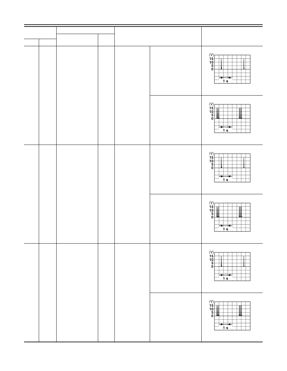
Room antenna (+)
(Center console)
Output
Ignition switch
OFF
When Intelligent Key is in
the passenger compart-
ment
When Intelligent Key is not
in the passenger compart-
ment
74
(Y)
Ground
Passenger door an-
tenna (-)
Output
When the pas-
senger door re-
quest switch is
operated with ig-
nition switch OFF
When Intelligent Key is in
the antenna detection area
When Intelligent Key is not
in the antenna detection
area
75
(LG)
Ground
Passenger door an-
tenna (+)
Output
When the pas-
senger door re-
quest switch is
operated with ig-
nition switch OFF
When Intelligent Key is in
the antenna detection area
When Intelligent Key is not
in the antenna detection
area
Terminal No.
(Wire color)
Description
Condition
Value
(Approx.)
Signal name
Input/
Output
+
–
JMKIA0062GB
JMKIA0063GB
JMKIA0062GB
JMKIA0063GB
JMKIA0062GB
JMKIA0063GB
PCS
BCM (BODY CONTROL MODULE)
PCS-87
< ECU DIAGNOSIS INFORMATION >
[POWER DISTRIBUTION SYSTEM]
C
D
E
F
G
H
I
J
K
L
B
A
O
P
N
76
(V)
Ground
Driver door antenna
(-)
Output
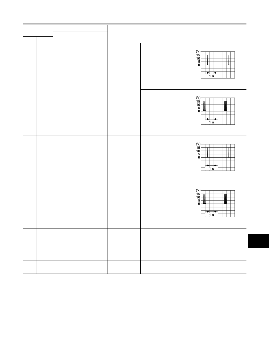
When the driver
door request
switch is operat-
ed with ignition
switch OFF
When Intelligent Key is in
the antenna detection area
When Intelligent Key is not
in the antenna detection
area
77
(P)
Ground
Driver door antenna
(+)
Output
When the driver
door request
switch is operat-
ed with ignition
switch OFF
When Intelligent Key is in
the antenna detection area
When Intelligent Key is not
in the antenna detection
area
80
(SB)
Ground
NATS antenna amp.
Input/
Output
During waiting
Ignition switch is pressed
while inserting Intelligent
Key into the key slot.
Just after pressing ignition
switch. Pointer of tester should
move.
81
(O)
Ground
NATS antenna amp.
Input/
Output
During waiting
Ignition switch is pressed
while inserting Intelligent
Key into the key slot.
Just after pressing ignition
switch. Pointer of tester should
move.
82
(BR)
Ground
Ignition relay [fuse
block (J/B)] control
Output
Ignition switch
OFF or ACC
0 V
ON
Battery voltage
Terminal No.
(Wire color)
Description
Condition
Value
(Approx.)
Signal name
Input/
Output
+
–
JMKIA0062GB
JMKIA0063GB
JMKIA0062GB
JMKIA0063GB
PCS-88
< ECU DIAGNOSIS INFORMATION >
[POWER DISTRIBUTION SYSTEM]
BCM (BODY CONTROL MODULE)
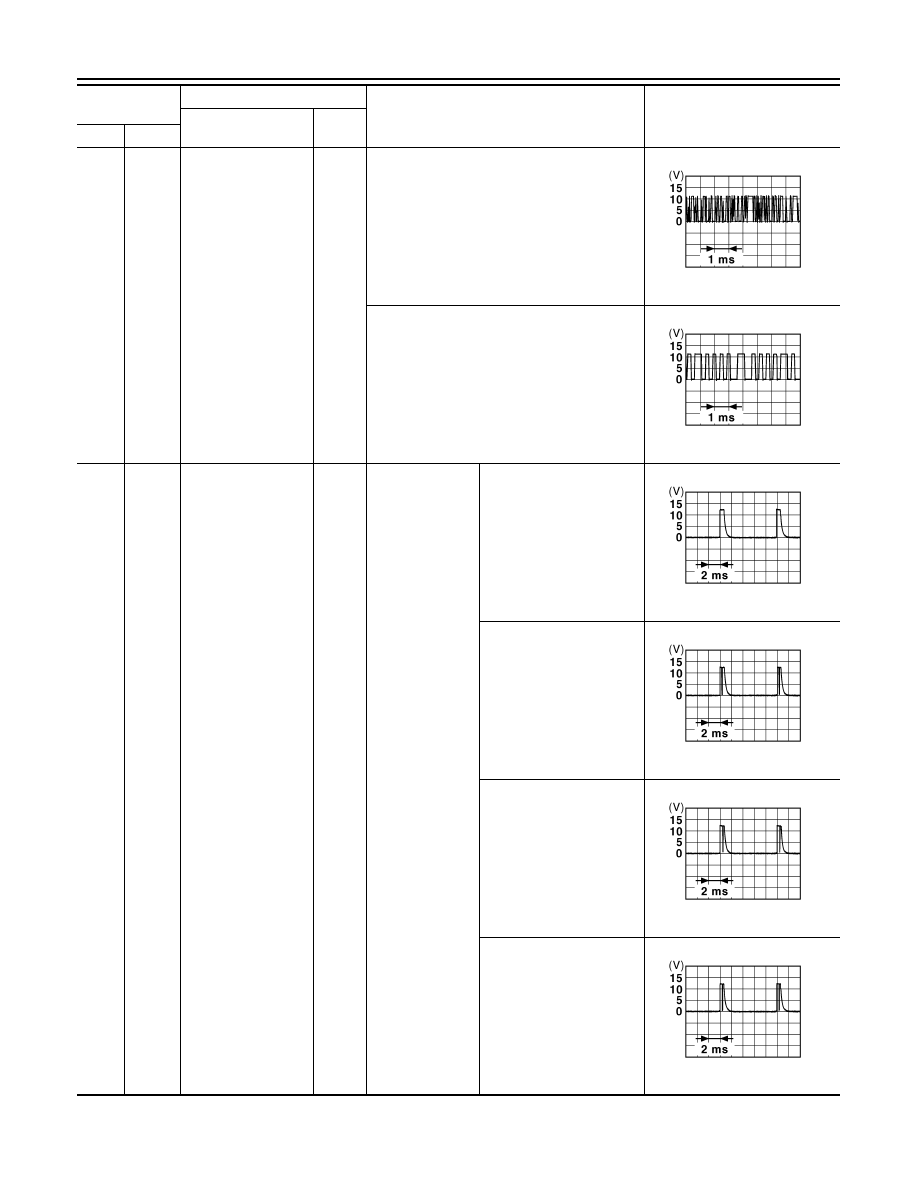
83
(P)
Ground
Remote keyless entry
receiver communica-
tion
Input/
Output
During waiting
When operating either button on Intelligent Key
87
(R)
Ground
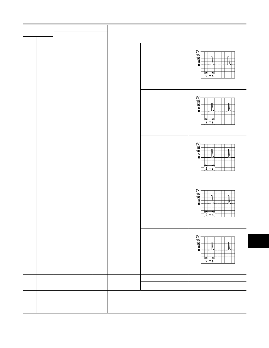
Combination switch
INPUT 5
Input
Combination
switch
All switches OFF
(Wiper intermittent dial 4)
1.4 V
Front fog lamp switch ON
(Wiper intermittent dial 4)
1.3 V
Rear wiper switch ON
(Wiper intermittent dial 4)
1.3 V
Any of the conditions below
with all switches OFF
• Wiper intermittent dial 1
• Wiper intermittent dial 2
• Wiper intermittent dial 6
• Wiper intermittent dial 7
1.3 V
Terminal No.
(Wire color)
Description
Condition
Value
(Approx.)
Signal name
Input/
Output
+
–
JMKIA0064GB
JMKIA0065GB
JPMIA0041GB
JPMIA0037GB
JPMIA0039GB
JPMIA0040GB
PCS
BCM (BODY CONTROL MODULE)
PCS-89
< ECU DIAGNOSIS INFORMATION >
[POWER DISTRIBUTION SYSTEM]
C
D
E
F
G
H
I
J
K
L
B
A
O
P
N
88
(GR)
Ground
Combination switch
INPUT 3
Input
Combination
switch
All switches OFF
(Wiper intermittent dial 4)
1.4 V
Lighting switch HI
(Wiper intermittent dial 4)
1.3 V
Lighting switch 2ND
(Wiper intermittent dial 4)
1.3 V
Rear washer switch ON
(Wiper intermittent dial 4)
1.3 V
Any of the conditions below
with all switches OFF
• Wiper intermittent dial 1
• Wiper intermittent dial 2
• Wiper intermittent dial 3
1.3 V
89
(BR)
Ground
Push-button ignition
switch (push switch)
Input
Push-button igni-
tion switch (push
switch)
Pressed
0 V
Not pressed
Battery voltage
90
(P)
Ground
CAN - L
Input/
Output
—
—
91
(L)
Ground
CAN - H
Input/
Output
—
—
Terminal No.
(Wire color)
Description
Condition
Value
(Approx.)
Signal name
Input/
Output
+
–
JPMIA0041GB
JPMIA0036GB
JPMIA0037GB
JPMIA0039GB
JPMIA0040GB
Нет комментариевНе стесняйтесь поделиться с нами вашим ценным мнением.
Текст