Nissan Murano Z51. Instruction — part 537

EC-156
< DTC/CIRCUIT DIAGNOSIS >
[VQ35DE]
P0101 MAF SENSOR
1.
Turn ignition switch OFF.
2.
Disconnect ECM harness connector.
3.
Check the continuity between MAF sensor harness connector and ECM harness connector.
4.
Also check harness for short to ground and short to power.
Is the inspection result normal?
YES
>> GO TO 7.
NO
>> Repair open circuit, short to ground or short to power in harness or connectors.
7.
CHECK MAF SENSOR INPUT SIGNAL CIRCUIT FOR OPEN AND SHORT
1.
Check the continuity between MAF sensor harness connector and ECM harness connector.
2.
Also check harness for short to ground and short to power.
Is the inspection result normal?
YES
>> GO TO 8.
NO
>> Repair open circuit, short to ground or short to power in harness or connectors.
8.
CHECK INTAKE AIR TEMPERATURE SENSOR
EC-165, "Component Inspection"
Is the inspection result normal?
YES
>> GO TO 9.
NO
>> Replace mass air flow sensor (with intake air temperature sensor).
9.
CHECK EVAP CONTROL SYSTEM PRESSURE SENSOR
EC-296, "Component Inspection"
Is the inspection result normal?
YES
>> GO TO 10.
NO
>> Replace EVAP control system pressure sensor.
10.
CHECK MASS AIR FLOW SENSOR
EC-156, "Component Inspection"
Is the inspection result normal?
YES
>> GO TO 11.
NO
>> Replace mass air flow sensor.
11.
CHECK INTERMITTENT INCIDENT
GI-39, "Intermittent Incident"
>> INSPECTION END
Component Inspection
INFOID:0000000005536561
1.
CHECK MASS AIR FLOW SENSOR-I
With CONSULT-III
1.
Reconnect all harness connectors disconnected.
2.
Start engine and warm it up to normal operating temperature.
3.
Connect CONSULT-III and select “DATA MONITOR” mode.
4.
Select “MAS A/F SE-B1” and check indication under the following conditions.
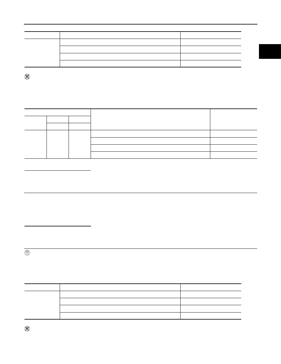
MAF sensor
ECM
Continuity
Connector
Terminal
Connector
Terminal
F4
4
F8
56
Existed
MAF sensor
ECM
Continuity
Connector
Terminal
Connector
Terminal
F4
3
F8
58
Existed
P0101 MAF SENSOR
EC-157
< DTC/CIRCUIT DIAGNOSIS >
[VQ35DE]
C
D
E
F
G
H
I
J
K
L
M
A
EC
N
P
O
*: Check for linear voltage rise in response to engine being increased to approximately 4,000 rpm.
Without CONSULT-III
1.
Reconnect all harness connectors disconnected.
2.
Start engine and warm it up to normal operating temperature.
3.
Check the voltage between ECM harness connector terminals under the following conditions.
*: Check for linear voltage rise in response to engine being increased to approximately 4,000 rpm.
Is the inspection result normal?
YES
>> INSPECTION END
NO
>> GO TO 2.
2.
CHECK FOR THE CAUSE OF UNEVEN AIR FLOW THROUGH MASS AIR FLOW SENSOR
Check for the cause of uneven air flow through mass air flow sensor. Refer to the following.
• Crushed air ducts
• Malfunctioning seal of air cleaner element
• Uneven dirt of air cleaner element
• Improper specification of intake air system parts
Is the inspection result normal?
YES
>> GO TO 4.
NO
>> GO TO 3.
3.
CHECK MASS AIR FLOW SENSOR-II
With CONSULT-III
1.
Repair or replace malfunctioning part.
2.
Start engine and warm it up to normal operating temperature.
3.
Connect CONSULT-III and select “DATA MONITOR” mode.
4.
Select “MAS A/F SE-B1” and check indication under the following conditions.
*: Check for linear voltage rise in response to engine being increased to approximately 4,000 rpm.
Without CONSULT-III
1.
Repair or replace malfunctioning part.
2.
Start engine and warm it up to normal operating temperature.
3.
Check the voltage between ECM harness connector terminals under the following conditions.
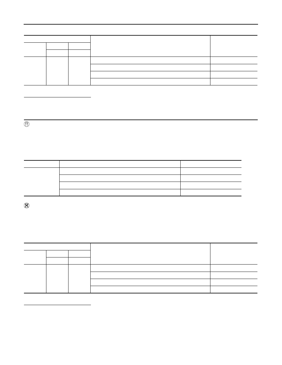
Monitor item
Condition
MAS A/F SE-B1 (V)
MAS A/F SE-B1
Ignition switch ON (Engine stopped.)
Approx. 0.4
Idle (Engine is warmed-up to normal operating temperature.)
0.9 - 1.2
2,500 rpm (Engine is warmed-up to normal operating temperature.)
1.6 - 1.9
Idle to approximately 4,000 rpm
0.9 - 1.2 to Approx. 2.4*
ECM
Condition
Voltage (V)
Connector
+
–
Terminal
Terminal
F8
58
(MAF sen-
sor signal)
56
(Sensor
ground)
Ignition switch ON (Engine stopped.)
Approx. 0.4
Idle (Engine is warmed-up to normal operating temperature.)
0.9 - 1.2
2,500 rpm (Engine is warmed-up to normal operating temperature.)
1.6 - 1.9
Idle to approximately 4,000 rpm
0.9 - 1.2 to Approx. 2.4*
Monitor item
Condition
MAS A/F SE-B1 (V)
MAS A/F SE-B1
Ignition switch ON (Engine stopped.)
Approx. 0.4
Idle (Engine is warmed-up to normal operating temperature.)
0.9 - 1.2
2,500 rpm (Engine is warmed-up to normal operating temperature.)
1.6 - 1.9
Idle to approximately 4,000 rpm
0.9 - 1.2 to Approx. 2.4*
EC-158
< DTC/CIRCUIT DIAGNOSIS >
[VQ35DE]
P0101 MAF SENSOR
*: Check for linear voltage rise in response to engine being increased to approximately 4,000 rpm.
Is the inspection result normal?
YES
>> INSPECTION END
NO
>> GO TO 4.
4.
CHECK MASS AIR FLOW SENSOR-III
With CONSULT-III
1.
Turn ignition switch OFF.
2.
Disconnect mass air flow sensor harness connector and reconnect it again.
3.
Start engine and warm it up to normal operating temperature.
4.
Connect CONSULT-III and select “DATA MONITOR” mode.
5.
Select “MAS A/F SE-B1” and check indication under the following conditions.
*: Check for linear voltage rise in response to engine being increased to approximately 4,000 rpm.
Without CONSULT-III
1.
Turn ignition switch OFF.
2.
Disconnect mass air flow sensor harness connector and reconnect it again.
3.
Start engine and warm it up to normal operating temperature.
4.
Check the voltage between ECM harness connector terminals under the following conditions.
*: Check for linear voltage rise in response to engine being increased to approximately 4,000 rpm.
Is the inspection result normal?
YES
>> INSPECTION END
NO
>> Clean or replace mass air flow sensor.
ECM
Condition
Voltage (V)
Connector
+
–
Terminal
Terminal
F8
58
(MAF sen-
sor signal)
56
(Sensor
ground)
Ignition switch ON (Engine stopped.)
Approx. 0.4
Idle (Engine is warmed-up to normal operating temperature.)
0.9 - 1.2
2,500 rpm (Engine is warmed-up to normal operating temperature.)
1.6 - 1.9
Idle to approximately 4,000 rpm
0.9 - 1.2 to Approx. 2.4*
Monitor item
Condition
MAS A/F SE-B1 (V)
MAS A/F SE-B1
Ignition switch ON (Engine stopped.)
Approx. 0.4
Idle (Engine is warmed-up to normal operating temperature.)
0.9 - 1.2
2,500 rpm (Engine is warmed-up to normal operating temperature.)
1.6 - 1.9
Idle to approximately 4,000 rpm
0.9 - 1.2 to Approx. 2.4*
ECM
Condition
Voltage (V)
Connector
+
–
Terminal
Terminal
F8
58
(MAF sen-
sor signal)
56
(Sensor
ground)
Ignition switch ON (Engine stopped.)
Approx. 0.4
Idle (Engine is warmed-up to normal operating temperature.)
0.9 - 1.2
2,500 rpm (Engine is warmed-up to normal operating temperature.)
1.6 - 1.9
Idle to approximately 4,000 rpm
0.9 - 1.2 to Approx. 2.4*
P0102, P0103 MAF SENSOR
EC-159
< DTC/CIRCUIT DIAGNOSIS >
[VQ35DE]
C
D
E
F
G
H
I
J
K
L
M
A
EC
N
P
O
P0102, P0103 MAF SENSOR
Description
INFOID:0000000005536562
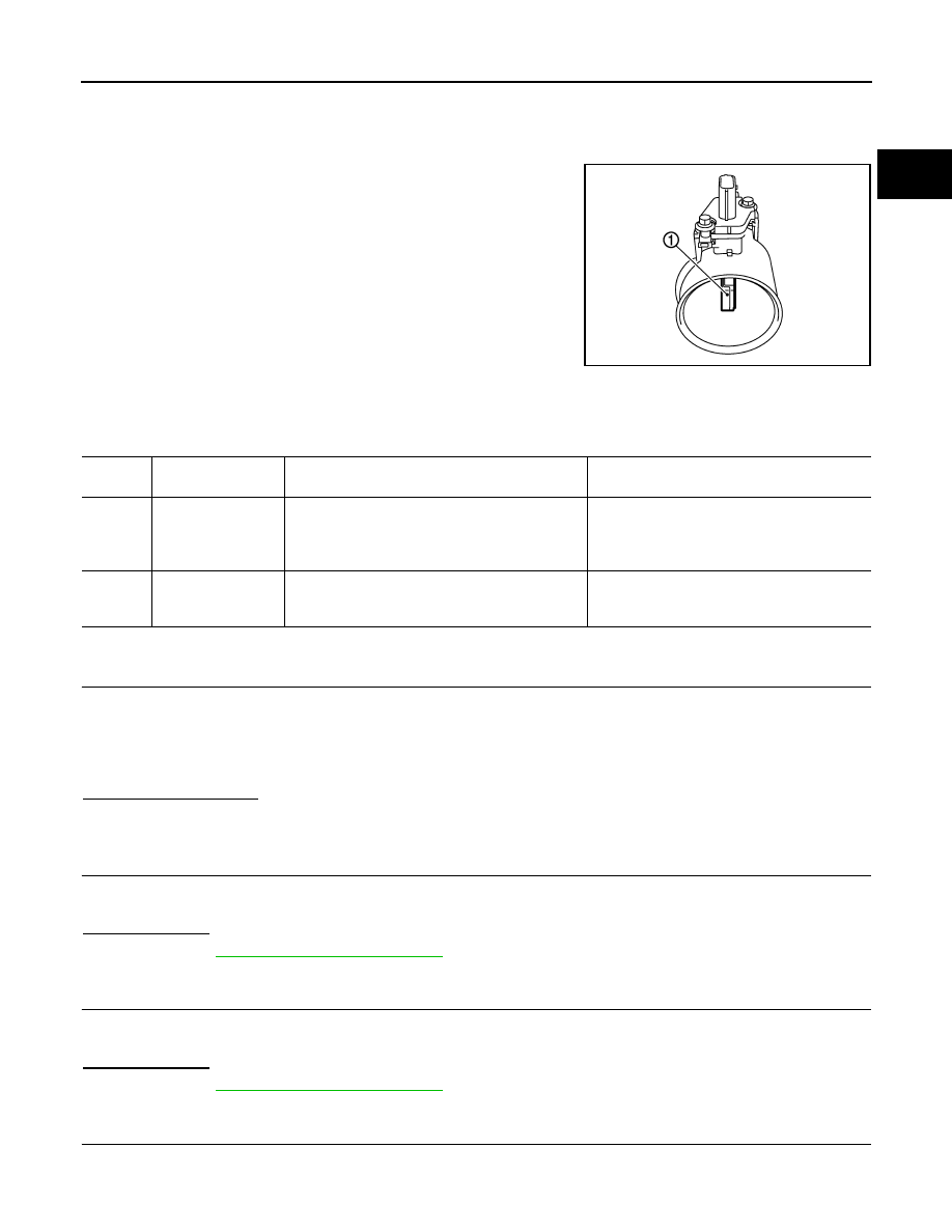
The mass air flow sensor (1) is placed in the stream of intake air. It
measures the intake flow rate by measuring a part of the entire
intake flow. The mass air flow sensor controls the temperature of the
hot wire to a certain amount. The heat generated by the hot wire is
reduced as the intake air flows around it. The greater air flow, the
greater the heat loss.
Therefore, the electric current supplied to hot wire is changed to
maintain the temperature of the hot wire as air flow increases. The
ECM detects the air flow by means of this current change.
DTC Logic
INFOID:0000000005536563
DTC DETECTION LOGIC
DTC CONFIRMATION PROCEDURE
1.
PRECONDITIONING
If DTC Confirmation Procedure has been previously conducted, always perform the following before conduct-
ing the next test.
1.
Turn ignition switch OFF and wait at least 10 seconds.
2.
Turn ignition switch ON.
3.
Turn ignition switch OFF and wait at least 10 seconds.
Which DTC is detected?
P0102 >> GO TO 2.
P0103 >> GO TO 3.
2.
PERFORM DTC CONFIRMATION PROCEDURE FOR DTC P0102
1.
Start engine and wait at least 5 seconds.
2.
Check DTC.
Is DTC detected?
YES
>> Go to
NO
>> INSPECTION END
3.
PERFORM DTC CONFIRMATION PROCEDURE FOR DTC P0103-I
1.
Turn ignition switch ON and wait at least 5 seconds.
2.
Check DTC.
Is DTC detected?
YES
>> Go to
NO
>> GO TO 4.
4.
PERFORM DTC CONFIRMATION PROCEDURE FOR DTC P0103-II
1.
Start engine and wait at least 5 seconds.
2.
Check DTC.
PBIA9559J
DTC No.
Trouble diagnosis
name
DTC detecting condition
Possible cause
P0102
Mass air flow sensor
circuit low input
An excessively low voltage from the sensor is sent
to ECM.
• Harness or connectors
(The sensor circuit is open or shorted.)
• Intake air leakage
• Mass air flow sensor
P0103
Mass air flow sensor
circuit high input
An excessively high voltage from the sensor is
sent to ECM.
• Harness or connectors
(The sensor circuit is open or shorted.)
• Mass air flow sensor
Нет комментариевНе стесняйтесь поделиться с нами вашим ценным мнением.
Текст