Nissan Murano Z51. Instruction — part 1018

MIR-28
< ECU DIAGNOSIS INFORMATION >
[WITH ADP]
DRIVER SEAT CONTROL UNIT
6
(R/L)
Ground
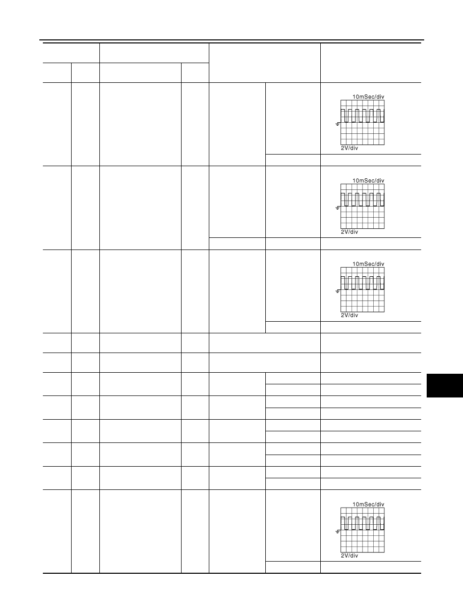
Reclining motor forward
output signal
Output
Seat reclining
Operate
(forward)
Battery voltage
Release
0
7
(L)
Ground
Lifting motor (rear) down
output signal
Output
Seat lifting (rear)
Operate
(down)
Battery voltage
Stop
0
8
(L/W)
Ground
Lifting motor (rear) up out-
put signal
Output
Seat lifting (rear)
Operate
(up)
Battery voltage
Stop
0
9
(L/R)
Ground
Lifting motor (front) down
output signal
Output
Seat lifting (front)
Operate
(down)
Battery voltage
Stop
0
10
(L/B)
Ground
Lifting motor (front) up out-
put signal
Output
Seat lifting (front)
Operate
(up)
Battery voltage
Stop
0
11
(G/B)
Ground
Sliding switch backward
signal
Input
Sliding switch
Operate
(backward)
0
Release
Battery voltage
12
(G/W)
Ground
Sliding switch forward sig-
nal
Input
Sliding switch
Operate
(forward)
0
Release
Battery voltage
13
(R/G)
Ground
Reclining switch backward
signal
Input
Reclining switch
Operate
(backward)
0
Release
Battery voltage
14
(R/W)
Ground
Reclining switch forward
signal
Input
Reclining switch
Operate
(forward)
0
Release
Battery voltage
15
(Y/B)
Ground
Lifting switch (rear) down
signal
Input
Lifting switch
(rear)
Operate
(down)
0
Release
Battery voltage
16
(Y/R)
Ground
Lifting switch (rear) up sig-
nal
Input
Seat lifting switch
(rear)
Operate
(up)
0
Release
Battery voltage
17
(LG/B)
Ground
Lifting switch (front) down
signal
Input
Lifting switch
(front)
Operate
(down)
0
Release
Battery voltage
18
(LG/R)
Ground
Lifting switch (front) up sig-
nal
Input
Seat lifting switch
(front)
Operate
(up)
0
Release
Battery voltage
19
(G/Y)
Ground
Sliding sensor signal
Input
Seat sliding
Operate
Stop
0 or 5
Terminal No.
(wire color)
Description
Condition
Voltage (V)
(Approx)
+
-
Signal name
Input/
Output
JMJIA0119ZZ
DRIVER SEAT CONTROL UNIT
MIR-29
< ECU DIAGNOSIS INFORMATION >
[WITH ADP]
C
D
E
F
G
H
I
J
K
M
A
B
MIR
N
O
P
20
(R/Y)
Ground
Reclining sensor signal
Input
Seat reclining
Operate
Stop
0 or 5
21
(L/Y)
Ground
Lifting sensor (rear) signal
Input
Seat lifting (rear)
Operate
Stop
0 or 5
22
(BR/Y)
Ground
Lifting sensor (front) signal
Input
Seat lifting (front)
Operate
Stop
0 or 5
23
(P)
—
CAN-H
—
—
—
24
(P/L)
—
CAN-L
—
—
—
25
(G/O)
Ground
Memory indictor 1 signal
Output
Memory indictor 1
Illuminate
1
Other than above
Battery voltage
26
(L/O)
Ground
Memory indictor 2 signal
Output
Memory indictor 2
Illuminate
1
Other than above
Battery voltage
27
(V)
Ground
Memory switch 1 signal
Input
Memory switch 1
Press
0
Other than above
5
28
(V/W)
Ground
Memory switch 2 signal
Input
Memory switch 2
Press
0
Other than above
5
29
(O/L)
Ground
Set switch signal
Input
Set switch
Press
0
Other than above
5
30
(BR)
Ground
Tilt sensor signal
Input
Tilt
Operate
Other than above
0 or 5
Terminal No.
(wire color)
Description
Condition
Voltage (V)
(Approx)
+
-
Signal name
Input/
Output
JMJIA0119ZZ
JMJIA0119ZZ
JMJIA0119ZZ
JMJIA0119ZZ

MIR-30
< ECU DIAGNOSIS INFORMATION >
[WITH ADP]
DRIVER SEAT CONTROL UNIT
31
(BR/W)
Ground
Telescopic sensor signal
Input
Telescopic
Operate
Other than above
0 or 5
32
(W/L)
Ground
UART communication
(TX/RX)
Input
Ignition switch ON
33
(W)
Ground
Sensor power supply
Output
—
Battery voltage
Terminal No.
(wire color)
Description
Condition
Voltage (V)
(Approx)
+
-
Signal name
Input/
Output
JMJIA1391ZZ

DRIVER SEAT CONTROL UNIT
MIR-31
< ECU DIAGNOSIS INFORMATION >
[WITH ADP]
C
D
E
F
G
H
I
J
K
M
A
B
MIR
N
O
P
Wiring Diagram - AUTOMATIC DRIVE POSITIONER CONTROL SYSTEM -
INFOID:0000000005716144
JCJWM0709GB
Нет комментариевНе стесняйтесь поделиться с нами вашим ценным мнением.
Текст