Nissan Murano Z51. Instruction — part 1480
INTAKE SENSOR
VTL-91
< REMOVAL AND INSTALLATION >
[WITH 7 INCH DISPLAY]
C
D
E
F
G
H
J
K
L
M
A
B
VTL
N
O
P
INTAKE SENSOR
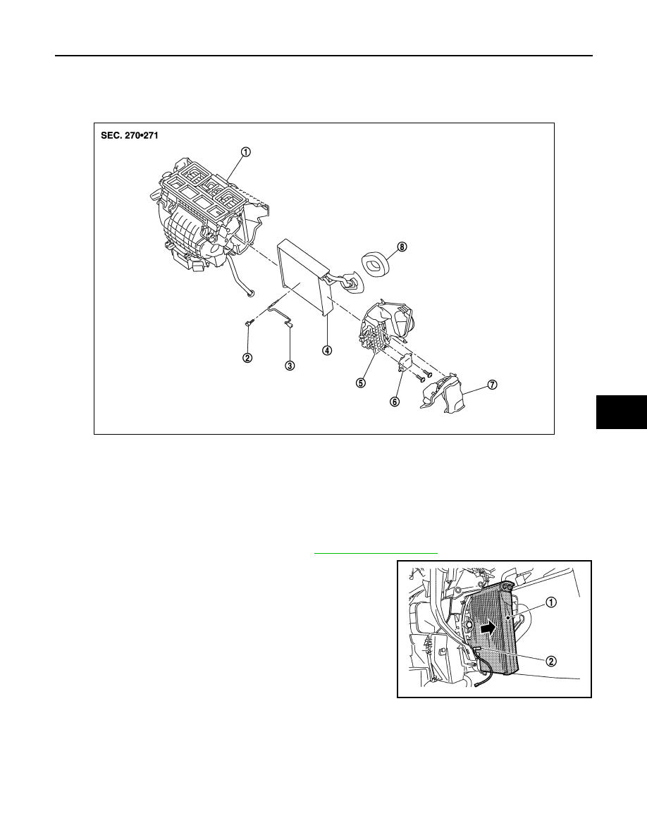
Exploded View
INFOID:0000000005517198
Removal and Installation
INFOID:0000000005517199
REMOVAL
1.
Remove the evaporator pipe assembly. Refer to
.
2.
Slide the evaporator (1) toward the right side of the vehicle, and
then remove the intake sensor (2).
INSTALLATION
Note the following, and install in the reverse order of removal.
CAUTION:
• Replace the O-ring with a new one. Apply a coat of compressor oil to the O-ring prior to installation.
• Install the intake sensor in the same position as the removed intake sensor when replacing the
intake sensor.
• Do not rotate the bracket insertion part when removing and installing the intake sensor.
• Check for refrigerant leakage when charging refrigerant.
1.
Heater & cooling unit assembly
2.
Intake sensor bracket
3.
Intake sensor
4.
Evaporator assembly
5.
Evaporator cover
6.
Air mix door motor (passenger side)
7.
Foot duct (right)
8.
Cooler pipe grommet
JPIIA1303ZZ
JPIIA0907ZZ

VTL-92
< REMOVAL AND INSTALLATION >
[WITH 7 INCH DISPLAY]
BLOWER UNIT
BLOWER UNIT
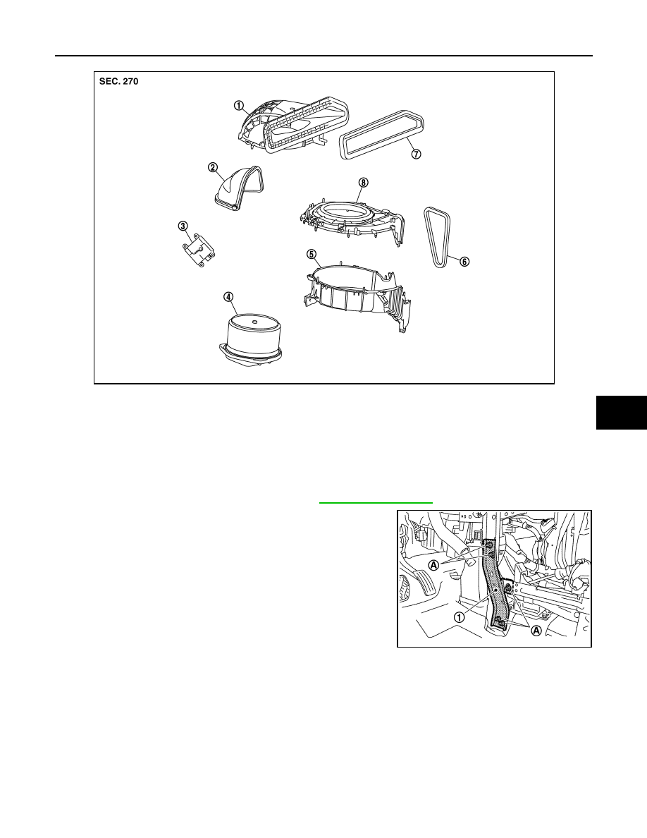
Exploded View
INFOID:0000000005517200
REMOVAL
DISASSEMBLY
1.
Blower unit assembly
2.
Heater & cooling unit assembly
3.
Steering member
4.
Instrument stay
5.
Instrument panel assembly
for symbols in the figure.
JPIIA1224GB
BLOWER UNIT
VTL-93
< REMOVAL AND INSTALLATION >
[WITH 7 INCH DISPLAY]
C
D
E
F
G
H
J
K
L
M
A
B
VTL
N
O
P
Removal and Installation
INFOID:0000000005517201
REMOVAL
1.
Remove the instrument panel assembly. Refer to
.
2.
Remove the mounting nuts (A), and then remove the instrument
panel stay (1).
3.
Disconnect the intake door motor and blower motor connectors.
1.
Shutter box case
2.
Intake door
3.
Intake door motor
4.
Blower motor assembly
5.
Intake lower case
6.
Outlet seal
7.
Intake seal
8.
Intake upper case
JPIIA0455ZZ
JPIIA0565ZZ
VTL-94
< REMOVAL AND INSTALLATION >
[WITH 7 INCH DISPLAY]
BLOWER UNIT
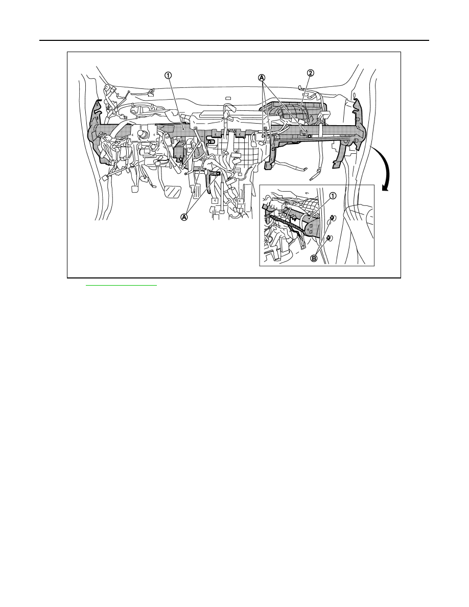
4.
Remove the heater & cooling unit assembly and blower unit mounting bolts (A).
for symbols in the figure.
5.
Remove the steering member mounting bolts (B) (right).
6.
And remove the blower unit (2) while pulling the steering member (1) to the front.
INSTALLATION
Install in the reverse order of removal.
JPIIA1230ZZ
Нет комментариевНе стесняйтесь поделиться с нами вашим ценным мнением.
Текст