Nissan Murano Z51. Instruction — part 1039
MWI-14
< SYSTEM DESCRIPTION >
METER SYSTEM
TACHOMETER : Component Description
INFOID:0000000005524823
ENGINE COOLANT TEMPERATURE GAUGE
ENGINE COOLANT TEMPERATURE GAUGE : System Diagram
INFOID:0000000005524824
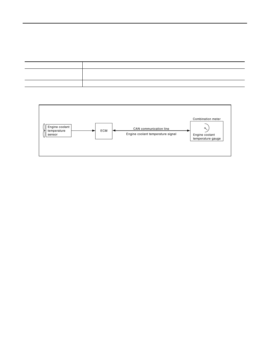
ENGINE COOLANT TEMPERATURE GAUGE : System Description
INFOID:0000000005524825
• ECM reads the engine coolant temperature signal from the engine coolant temperature sensor and transmits
the signal to the combination meter via CAN communication.
• The combination meter indicates the engine coolant temperature to the engine coolant temperature gauge
according to the engine coolant temperature signal received via CAN communication.
A.
Lower right side of rear seat
B.
Engine room (RH)
C.
Engine front side
D.
Engine room (LH)
E.
Front bumper (left back)
F.
Engine room (LH)
G.
Engine room (LH)
H.
Behind the combination meter
I.
Lower left side of rear seat
Unit
Description
Combination meter
Indicates the engine speed to the tachometer according to the engine speed signal received from
ECM via CAN communication.
ECM
Transmits the engine speed signal to the combination meter with CAN communication line.
JSNIA0291GB

MWI
METER SYSTEM
MWI-15
< SYSTEM DESCRIPTION >
C
D
E
F
G
H
I
J
K
L
M
B
A
O
P
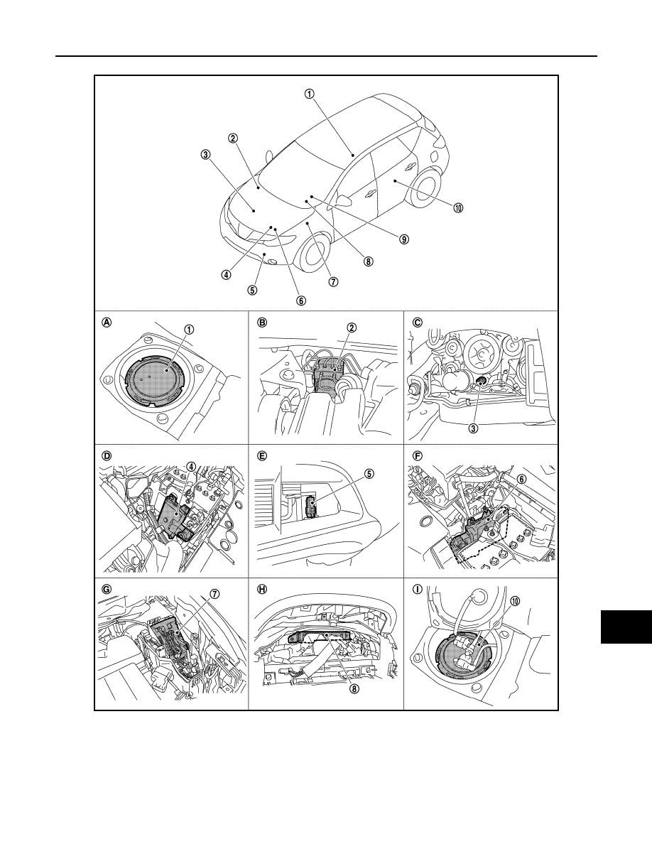
ENGINE COOLANT TEMPERATURE GAUGE : Component Parts Location
INFOID:0000000005524826
JPNIA0813ZZ
1.
Fuel level sensor unit (sub)
2.
ABS actuator and electric unit (con-
trol unit)
3.
Oil pressure switch
4.
TCM
5.
Ambient sensor
6.
ECM
7.
IPDM E/R
8.
BCM
9.
Combination meter
10.
Fuel level sensor unit and fuel pump
(main)
MWI-16
< SYSTEM DESCRIPTION >
METER SYSTEM
ENGINE COOLANT TEMPERATURE GAUGE : Component Description
INFOID:0000000005524827
FUEL GAUGE
FUEL GAUGE : System Diagram
INFOID:0000000005524828
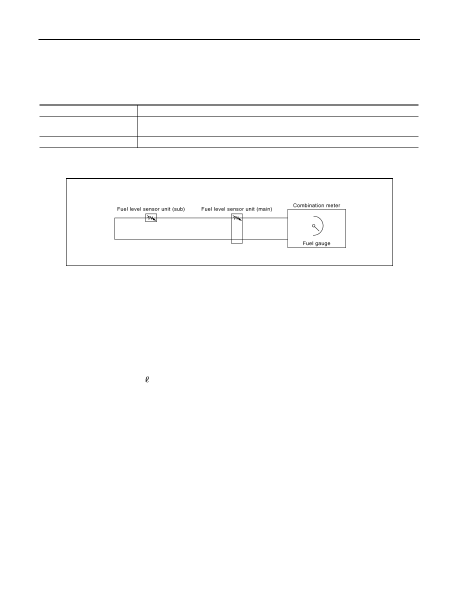
FUEL GAUGE : System Description
INFOID:0000000005524829
CONTROL OUTLINE
The combination meter reads the fuel level sensor signal from the fuel level sensor unit and indicates the fuel
level to the fuel gauge.
REFUEL CONTROL
The combination meter accelerates the fuel gauge segment if the all conditions listed below are met, or the
ignition switch is ON from OFF.
• Ignition switch is ON position.
• The vehicle is not moving.
• The fuel level change by 15 (4 US gal, 3-1/4 lmp gal) or more.
A.
Lower right side of rear seat
B.
Engine room (RH)
C.
Engine front side
D.
Engine room (LH)
E.
Front bumper (left back)
F.
Engine room (LH)
G.
Engine room (LH)
H.
Behind the combination meter
I.
Lower left side of rear seat
Unit
Description
Combination meter
Indicates the engine coolant temperature to the engine coolant temperature gauge according to the
engine coolant temperature signal received from ECM via CAN communication.
ECM
Transmits the engine coolant temperature signal to the combination meter via CAN communication.
JSNIA0511GB
MWI
METER SYSTEM
MWI-17
< SYSTEM DESCRIPTION >
C
D
E
F
G
H
I
J
K
L
M
B
A
O
P
FUEL GAUGE : Component Parts Location
INFOID:0000000005524830
JPNIA0813ZZ
1.
Fuel level sensor unit (sub)
2.
ABS actuator and electric unit (con-
trol unit)
3.
Oil pressure switch
4.
TCM
5.
Ambient sensor
6.
ECM
7.
IPDM E/R
8.
BCM
9.
Combination meter
10.
Fuel level sensor unit and fuel pump
(main)
Нет комментариевНе стесняйтесь поделиться с нами вашим ценным мнением.
Текст