Nissan Murano Z51. Instruction — part 93
AV
AV CONTROL UNIT
AV-151
< ECU DIAGNOSIS INFORMATION >
[BOSE AUDIO WITHOUT NAVIGATION]
C
D
E
F
G
H
I
J
K
L
M
B
A
O
P
ECU DIAGNOSIS INFORMATION
AV CONTROL UNIT
Reference Values
INFOID:0000000005528579
VALUES ON THE DIAGNOSIS TOOL
CONSULT-III MONITOR ITEM
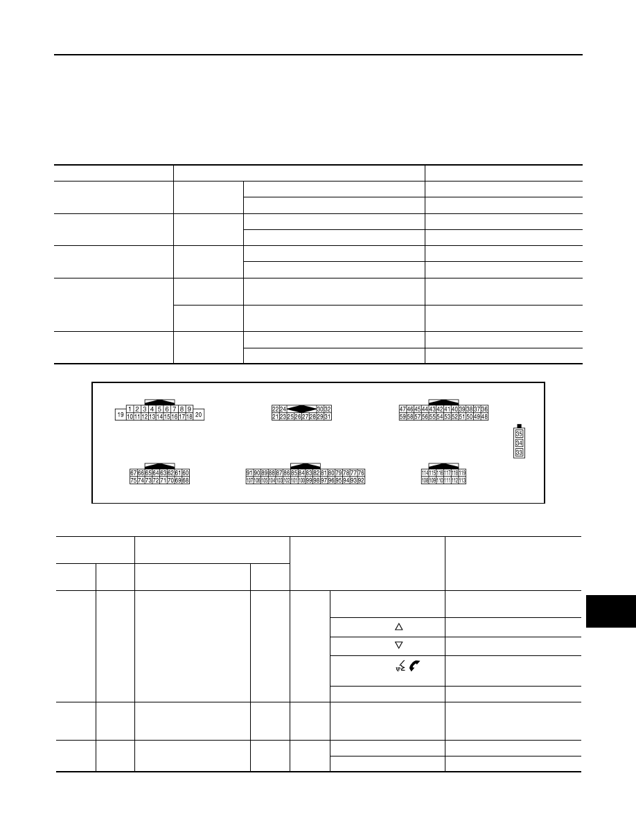
TERMINAL LAYOUT
PHYSICAL VALUES
Monitor Item
Condition
Value/Status
VHCL SPD SIG
Ignition switch
ON
Vehicle speed > 0 km/h (0 MPH)
On
Vehicle speed = 0 km/h (0 MPH)
Off
PKB SIG
Ignition switch
ON
Parking brake is applied.
On
Parking brake is released.
Off
ILLUM SIG
Ignition switch
ON
Light switch ON
On
Light switch OFF
Off
IGN SIG
Ignition switch
ON
—
On
Ignition switch
ACC
—
Off
REV SIG
Ignition switch
ON
Selector lever in R position
On
Selector lever in any position other than R
Off
JPNIA0009ZZ
Terminal
(Wire color)
Description
Condition
Reference value
(Approx.)
+
–
Signal name
Input/
Output
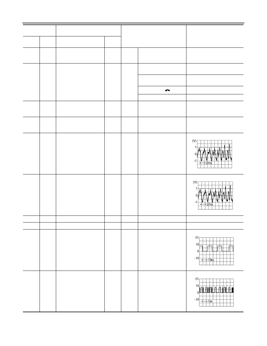
6
(BR)
15
(L)
Steering switch signal A
Input
Ignition
switch
ON
Keep pressing SOURCE
switch.
0 V
Keep pressing
switch.
0.7 V
Keep pressing
switch.
1.3 V
Keep pressing
switch.
2.0 V
Except for above.
3.3 V
7
(R)
Ground
ACC power supply
Input
Ignition
switch
ACC
—
Battery voltage
9
(R)
Ground
Illumination signal
Input
OFF
Lighting switch is OFF.
0 V
Lighting switch is ON.
12.0 V
AV-152
< ECU DIAGNOSIS INFORMATION >
[BOSE AUDIO WITHOUT NAVIGATION]
AV CONTROL UNIT
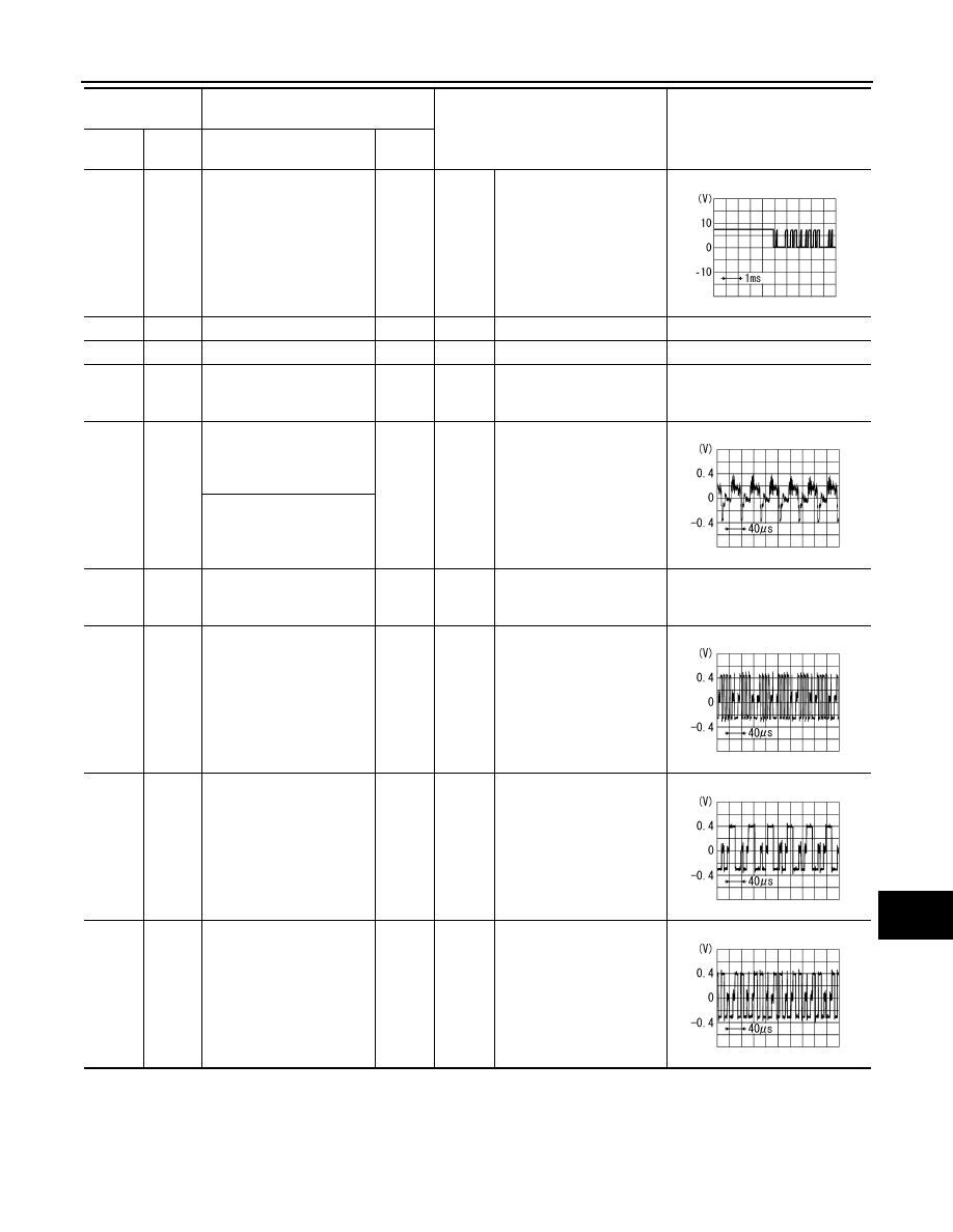
15
(L)
Ground
Steering switch signal GND
—
Ignition
switch
ON
—
0 V
16
(G)
15
(L)
Steering switch signal B
Input
Ignition
switch
ON
Keep pressing VOL DOWN
switch.
0 V
Keep pressing VOL UP
switch.
0.7 V
Keep pressing
switch.
1.3 V
Except for above.
3.3 V
19
(Y)
Ground
Battery power supply
Input
Ignition
switch
OFF
—
Battery voltage
20
(B)
Ground
Ground
—
Ignition
switch
ON
—
0 V
22
(G)
21
(B)
Satellite radio sound signal
LH
Input
Ignition
switch
ON
When satellite radio mode
is selected.
24
(W)
23
(R)
Satellite radio sound signal
RH
Input
Ignition
switch
ON
When satellite radio mode
is selected.
25
—
Shield
—
—
—
—
26
—
Shield
—
—
—
—
28
(R)
Ground
Request signal
(SAT
→
CONT)
Input
Ignition
switch
ON
When satellite radio mode
is selected.
29
(W)
Ground
Communication signal
(SAT
→
CONT)
Input
Ignition
switch
ON
When satellite radio mode
is selected.
Terminal
(Wire color)
Description
Condition
Reference value
(Approx.)
+
–
Signal name
Input/
Output
SKIB3609E
SKIB3609E
SKIA9299J
SKIA9300J
AV
AV CONTROL UNIT
AV-153
< ECU DIAGNOSIS INFORMATION >
[BOSE AUDIO WITHOUT NAVIGATION]
C
D
E
F
G
H
I
J
K
L
M
B
A
O
P
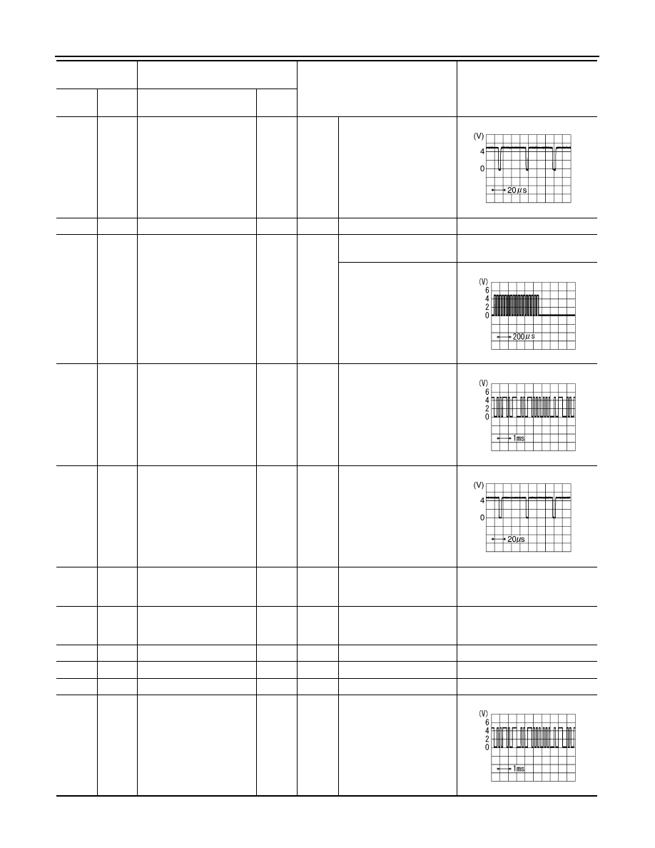
30
(B)
Ground
Communication signal
(CONT
→
SAT)
Output
Ignition
switch
ON
When satellite radio mode
is selected.
33
—
FM sub
Input
—
—
—
34
—
AM–FM main
Input
—
—
—
35
Ground
Antenna amp. ON signal
Output
Ignition
switch
ACC
—
12.0 V
36
(L)
37
(P)
Without DVD player
models
• Composite image signal
(AUX/Camera image)
Output
Ignition
switch
ON
When composite image is
displayed.
With DVD player models
• Composite image signal
(DVD/AUX/Camera im-
age)
37
(P)
Ground
Composite image ground
—
Ignition
switch
ON
—
0 V
38
(Y)
Ground
RGB image signal (B: blue)
Output
Ignition
switch
ON
Start confirmation/adjust-
ment mode, and then dis-
play color bar by selecting
“Color Spectrum Bar” on
DISPLAY DIAGNOSIS
screen.
39
(L)
Ground
RGB image signal (G:
green)
Output
Ignition
switch
ON
Start confirmation/adjust-
ment mode, and then dis-
play color bar by selecting
“Color Spectrum Bar” on
DISPLAY DIAGNOSIS
screen.
40
(G)
Ground
RGB image signal (R: red)
Output
Ignition
switch
ON
Start confirmation/adjust-
ment mode, and then dis-
play color bar by selecting
“Color Spectrum Bar” on
DISPLAY DIAGNOSIS
screen.
Terminal
(Wire color)
Description
Condition
Reference value
(Approx.)
+
–
Signal name
Input/
Output
SKIA9301J
SKIB2251J
SKIB2237J
SKIB2236J
SKIB2238J
AV-154
< ECU DIAGNOSIS INFORMATION >
[BOSE AUDIO WITHOUT NAVIGATION]
AV CONTROL UNIT
41
(B)
Ground
RGB synchronizing signal
Output
Ignition
switch
ON
—
42
—
Shield
—
—
—
—
43
(W)
Ground
RGB area (YS) signal
Output
Ignition
switch
ON
When RGB image is dis-
played.
5.0 V
When AUX or camera im-
age is displayed.
44
(G)
Ground
Communication signal
(DISP
→
CONT)
Input
Ignition
switch
ON
When adjusting display
brightness.
45
(G)
Ground
Horizontal synchronizing
(HP) signal
Input
Ignition
switch
ON
—
46
(LG)
Ground
Signal GND
—
Ignition
switch
ON
—
0 V
47
(O)
Ground
Signal VCC (front display
unit power supply)
Output
Ignition
switch
ACC
—
9.0 V
49
—
Shield
—
—
—
—
50
—
Shield
—
—
—
—
55
—
Shield
—
—
—
—
56
(R)
Ground
Communication signal
(CONT
→
DISP)
Output
Ignition
switch
ON
When adjusting display
brightness.
Terminal
(Wire color)
Description
Condition
Reference value
(Approx.)
+
–
Signal name
Input/
Output
SKIB3603E
PKIB4948J
PKIB5039J
SKIB3601E
PKIB5039J
Нет комментариевНе стесняйтесь поделиться с нами вашим ценным мнением.
Текст