Nissan Murano Z51. Instruction — part 1048
MWI-50
< DTC/CIRCUIT DIAGNOSIS >
METER CONTROL SWITCH SIGNAL CIRCUIT
NO
>> Replace the meter control switch.
MWI
OIL PRESSURE SWITCH SIGNAL CIRCUIT
MWI-51
< DTC/CIRCUIT DIAGNOSIS >
C
D
E
F
G
H
I
J
K
L
M
B
A
O
P
OIL PRESSURE SWITCH SIGNAL CIRCUIT
Description
INFOID:0000000005525068
Detects the engine oil pressure and transmits the oil pressure switch signal to IPDM E/R.
Component Function Check
INFOID:0000000005525069
1.
CHECK COMBINATION METER INPUT SIGNAL
Select the “Data Monitor” for the “METER/M&A” and check the “OIL W/L” monitor value.
>> INSPECTION END
Diagnosis Procedure
INFOID:0000000005525070
1.
CHECK OIL PRESSURE SWITCH CIRCUIT
1.
Turn ignition switch OFF.
2.
Disconnect IPDM E/R connector and oil pressure switch connector.
3.
Check continuity between IPDM E/R harness connector terminal and oil pressure switch harness connec-
tor terminal.
4.
Check continuity between IPDM E/R harness connector terminal and ground.
Is the inspection result normal?
YES
>> INSPECTION END
NO
>> Repair harness or connector.
Component Inspection
INFOID:0000000005525071
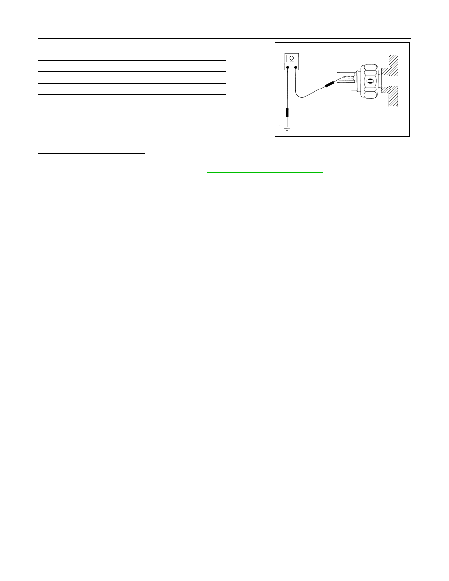
1.
CHECK OIL PRESSURE SWITCH
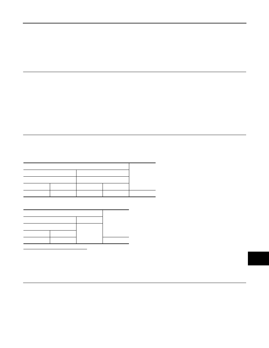
“OIL W/L”
Ignition switch ON
: On
Engine running
: Off
Terminals
Continuity
(+)
(
−
)
IPDM E/R
Oil pressure switch
Connector
Terminal
Connector
Terminal
F12
75
F63
1
Existed
Terminals
Continuity
(+)
(
−
)
IPDM E/R
Ground
Connector
Terminal
F12
75
Not existed
MWI-52
< DTC/CIRCUIT DIAGNOSIS >
OIL PRESSURE SWITCH SIGNAL CIRCUIT
Check continuity between oil pressure switch and ground.
Is the inspection result normal?
YES
>> INSPECTION END
NO
>> Replace oil pressure switch. Refer to
EM-43, "Removal and Installation"
.
Condition
Continuity
Engine stopped
Existed
Engine running
Not existed
ELF0044D
MWI
PARKING BRAKE SWITCH SIGNAL CIRCUIT
MWI-53
< DTC/CIRCUIT DIAGNOSIS >
C
D
E
F
G
H
I
J
K
L
M
B
A
O
P
PARKING BRAKE SWITCH SIGNAL CIRCUIT
Description
INFOID:0000000005524886
Transmits the parking brake switch signal to the combination meter.
Diagnosis Procedure
INFOID:0000000005524887
1.
CHECK COMBINATION METER INPUT SIGNAL
1.
Turn ignition switch ON.
2.
Check the voltage between combination meter harness connector terminal and ground.
Is the inspection result normal?
YES
>> INSPECTION END
NO
>> GO TO 2.
2.
CHECK PARKING BRAKE SWITCH SIGNAL CIRCUIT
1.
Turn ignition switch OFF.
2.
Disconnect combination meter connector and parking brake switch connector.
3.
Check continuity between combination meter harness connector terminal and parking brake switch har-
ness connector terminal.
4.
Check continuity between combination meter harness connector terminal and ground.
Is the inspection result normal?
YES
>> INSPECTION END
NO
>> Repair harness or connector.
Component Inspection
INFOID:0000000005524888
1.
CHECK PARKING BRAKE SWITCH
Check parking brake switch. Refer to
BRC-78, "Component Inspection"
Is the inspection result normal?
YES
>> INSPECTION END.
NO
>> Replace parking brake switch.
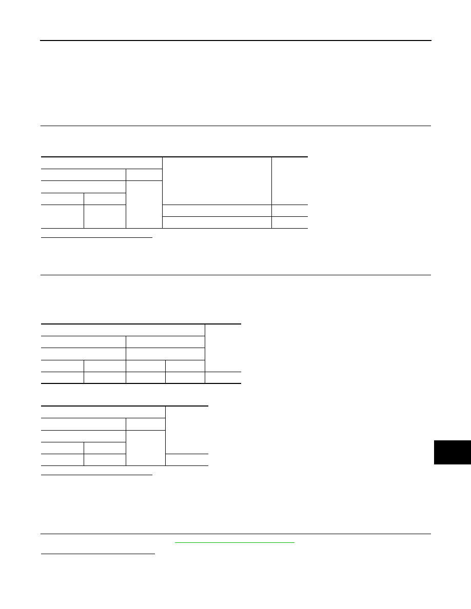
Terminals
Condition
Voltage
(Approx.)
(+)
(-)
Combination meter
Ground
Connector
Terminal
M34
26
When parking brake is applied
0 V
When parking brake is released
5 V
Terminals
Continuity
(+)
(-)
Combination meter
Parking brake switch
Connector
Terminal
Connector
Terminal
M34
26
E27
1
Existed
Terminals
Continuity
(+)
(-)
Combination meter
Ground
Connector
Terminal
M34
26
Not existed
Нет комментариевНе стесняйтесь поделиться с нами вашим ценным мнением.
Текст