Nissan Murano Z51. Instruction — part 1213
SE-40
< DTC/CIRCUIT DIAGNOSIS >
VEHICLE SPEED SIGNAL CIRCUIT
VEHICLE SPEED SIGNAL CIRCUIT
Description
INFOID:0000000005518191
Transmits vehicle speed signal to rear seatback power return control unit.
Component Function Check
INFOID:0000000005518192
1.
CHECK FUNCTION
Check that the rear seatback rises when pressing and holding the power return switch.
Is the inspection result normal?
YES
>> Vehicle speed signal circuit is OK.
NO
>> Refer to
Diagnosis Procedure
INFOID:0000000005518193
1.
CHECK VEHICLE SPEED OPERATION
1.
Check speed meter operate normally.
Is the inspection result normal?
YES
>> GO TO 2.
NO
>> Refer to
2.
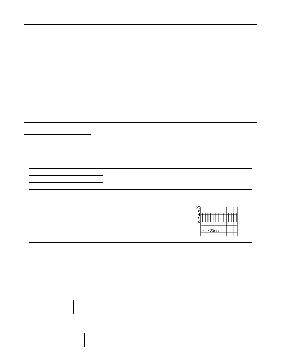
CHECK VEHICLE SPEED INPUT SIGNAL
Check voltage between rear seatback power return control unit harness connector and ground.
Is the inspection result normal?
YES
>> GO TO 3.
NO
>> Refer to
3.
CHECK VEHICLE SPEED SIGNAL CIRCUIT
1.
Disconnect rear seatback power return control unit connector and combination meter connector.
2.
Check continuity between power return control unit harness connector and combination meter harness
connector.
3.
Check continuity between rear seatback power return control unit harness connector and ground.
(+)
(–)
Condition
Voltage (V)
(Approx.)
Rear seatback power return control unit
Connector
Terminal
B493
24
Ground
When vehicle speed is ap-
prox.40 km/h (25MPH)
NOTE:
Maximum voltage may be 12V due
to specifications (connected units)
SKIA6649J
Rear seatback power return control unit
Combination meter
Continuity
Connector
Terminal
Connector
Terminal
B493
24
M34
31
Existed
Rear seatback power return control unit
Ground
Continuity
Connector
Terminal
B493
24
Not existed
VEHICLE SPEED SIGNAL CIRCUIT
SE-41
< DTC/CIRCUIT DIAGNOSIS >
C
D
E
F
G
H
I
K
L
M
A
B
SE
N
O
P
Is the inspection result normal?
YES
>> GO TO 4.
NO
>> Repair or replace harness.
4.
CHECK INTERMITTENT INCIDENT
GI-39, "Intermittent Incident"
.
>> INSPECTION END
SE-42
< DTC/CIRCUIT DIAGNOSIS >
TILT&TELESCOPIC SWITCH
TILT&TELESCOPIC SWITCH
Description
INFOID:0000000005518194
Tilt & telescopic switch as a unit, transmits switch operation signal to automatic drive positioner control unit.
Component Function Check
INFOID:0000000005518195
1.
CHECK TILT & TELESCOPIC SWITCH FUNCTION
Check tilt & telescopic operation with tilt & telescopic switch.
Is the inspection results normal?
YES
>> Tilt & telescopic switch is OK.
NO
>> Refer to
Diagnosis Procedure
INFOID:0000000005518196
1.
CHECK AUTOMATIC DRIVE POSITIONER CONTROL UNIT OUTPUT SIGNAL
1.
Turn ignition switch OFF.
2.
Disconnect tilt & telescopic switch connector.
3.
Check voltage between tilt & telescopic switch harness connector and ground.
Is the inspection result normal?
YES
>> GO TO 3.
NO
>> GO TO 2.
2.
CHECK TILT & TELESCOPIC SWITCH SIGNAL CIRCUIT
1.
Disconnect automatic drive positioner control unit connector.
2.
Check continuity between tilt & telescopic switch harness connector and automatic drive positioner control
unit harness connector.
3.
Check continuity between tilt & telescopic switch harness connector and ground.
Is the inspection result normal?
(+)
(
−
)
Voltage (V)
(Approx.)
Tilt & telescopic switch
Connector
Terminal
M102
2
Ground
5
3
4
5
Tilt & telescopic switch
Automatic drive positioner control unit
Continuity
Connector
Terminal
Connector
Terminal
M102
2
M75
1
Existed
3
13
4
19
5
7
Tilt & telescopic switch
Ground
Continuity
Connector
Terminal
M102
2
Not existed
3
4
5
TILT&TELESCOPIC SWITCH
SE-43
< DTC/CIRCUIT DIAGNOSIS >
C
D
E
F
G
H
I
K
L
M
A
B
SE
N
O
P
YES
>> Replace automatic drive positioner control unit. Refer to
SE-140, "Removal and Installation"
.
NO
>> Repair or replace harness.
3.
CHECK TILT & TELESCOPIC SWITCH GROUND CIRCUIT
Check continuity between tilt & telescopic switch harness connector and ground.
Is the inspection result normal?
YES
>> GO TO 4.
NO
>> Repair or replace harness.
4.
CHECK TILT & TELESCOPIC SWITCH
Check tilt & telescopic switch.
Refer to
Is the inspection result normal?
YES
>> GO TO 5.
NO
>> Replace tilt & telescopic switch.Refer to
SE-141, "Removal and Installation"
.
5.
CHECK INTERMITTENT INCIDENT
GI-39, "Intermittent Incident"
.
>> INSPECTION END
Component Inspection
INFOID:0000000005518197
1.
CHECK TILT & TELESCOPIC SWITCH
1.
Turn ignition switch OFF.
2.
Disconnect tilt & telescopic switch connector.
3.
Check continuity between tilt & telescopic switch terminals.
Is the inspection result normal?
YES
>> Tilt & telescopic switch is OK.
NO
>> Replace tilt & telescopic switch. Refer to
SE-141, "Removal and Installation"
Tilt & telescopic switch
Ground
Continuity
Connector
Terminal
M102
1
Existed
Terminal
Condition
Continuity
2
1
Tilt & telescopic switch
Upward position
Existed
Other than above
Not existed
3
Downward position
Existed
Other than above
Not existed
4
Backward position
Existed
Other than above
Not existed
5
Forward position
Existed
Other than above
Not existed
Нет комментариевНе стесняйтесь поделиться с нами вашим ценным мнением.
Текст