Nissan Murano Z51. Instruction — part 885

MAGNET CLUTCH
HAC-195
< DTC/CIRCUIT DIAGNOSIS >
[WITH 7 INCH DISPLAY]
C
D
E
F
G
H
J
K
L
M
A
B
HAC
N
O
P
MAGNET CLUTCH
Description
INFOID:0000000005514741
The magnet clutch drives the compressor, by an IPDM E/R signal.
Component Function Check
INFOID:0000000005514742
1.
FUNCTION INSPECTION
1.
Press AUTO switch.
2.
“AUTO” is indicated on the display.
3.
Press the A/C switch.
4.
Check that the indicator of the A/C switch turns on. Check visually and by sound that the compressor is
operating (the discharge air temperature or fan speed varies depending on the ambient temperature, in-
vehicle temperature, and temperature setting).
5.
Press the A/C switch again.
6.
Check that the indicator of the A/C switch turns OFF. Check visually and by sound that the compressor
stops.
Does it operate normally?
YES
>> INSPECTION END
NO
>> Perform trouble diagnosis for the compressor. Refer to
HAC-195, "Diagnosis Procedure"
Diagnosis Procedure
INFOID:0000000005514743
1.
INSPECTION IN AUTO ACTIVE TEST MODE
Perform “AUTO ACTIVE TEST”. Refer to
PCS-10, "Diagnosis Description"
Does it operate normally?
YES
>> GO TO 5.
NO
>> GO TO 2.
2.
CHECK MAGNET CLUTCH
1.
Turn the ignition switch OFF.
2.
Disconnect the magnet clutch connector.
3.
Directly apply the battery voltage to the magnet clutch. Check for operation visually and by sound.
Does it operate normally?
YES
>> GO TO 3.
NO
>> Replace the compressor.
3.
CHECK MAGNET CLUTCH CIRCUIT CONTINUITY
1.
Turn the ignition switch OFF.
2.
Disconnect IPDM E/R connector.
3.
Check continuity between magnet clutch harness connector and IPDM E/R harness connector.
Is the inspection result normal?
YES
>> GO TO 4.
NO
>> Repair harness or connector.
4.
CHECK FUSE
Check 10A fuse (No. 49).
NOTE:
Refer to
PG-115, "Fuse, Connector and Terminal Arrangement"
Is the inspection result normal?
YES
>> Replace IPDM E/R.
IPDM E/R
Compressor
Continuity
Connector
Terminal
Connector
Terminal
F12
48
F18
1
Existed

HAC-196
< DTC/CIRCUIT DIAGNOSIS >
[WITH 7 INCH DISPLAY]
MAGNET CLUTCH
NO
>> Replace the fuse after repairing the applicable circuit.
5.
CHECK WITH SELF-DIAGNOSIS FUNCTION OF CONSULT-III
1.
Using CONSULT-III, perform “SELF-DIAGNOSIS RESULTS” of HVAC.
2.
Check if any DTC No. is displayed in the self-diagnosis results.
NOTE:
If DTC is displayed along with DTC U1000 or U1010, first diagnose the DTC U1000 or U1010. Refer to
Is any DTC No. displayed?
YES
>> Perform the diagnosis that is applicable to the sensor and actuator. Refer to
.
NO
>> GO TO 6.
6.
CHECK A/C AUTO AMP. INPUT SIGNAL
Using CONSULT-III, check “On/Off” of “COMP REQ SIG” and “FAN REQ SIG” in “DATA MONITOR” of HVAC.
Refer to
HAC-161, "CONSULT-III Function"
Is the inspection result normal?
YES
>> GO TO 7.
NO
>> Replace A/C auto amp.
7.
CHECK REFRIGERANT PRESSURE SENSOR
Check refrigerant pressure sensor. Refer to
.
Is the inspection result normal?
YES
>> INSPECTION END
NO
>> Repair or replace malfunctioning parts.
A/C SWITCH ON
: COMP REQ SIG On
A/C SWITCH OFF
: COMP REQ SIG Off
FAN CONTROL DIAL ON
: FAN REQ SIG On
FAN CONTROL DIAL OFF
: FAN REQ SIG Off
POWER SUPPLY AND GROUND CIRCUIT
HAC-197
< DTC/CIRCUIT DIAGNOSIS >
[WITH 7 INCH DISPLAY]
C
D
E
F
G
H
J
K
L
M
A
B
HAC
N
O
P
POWER SUPPLY AND GROUND CIRCUIT
A/C AUTO AMP.
A/C AUTO AMP. : Description
INFOID:0000000005514744
COMPONENT DESCRIPTION
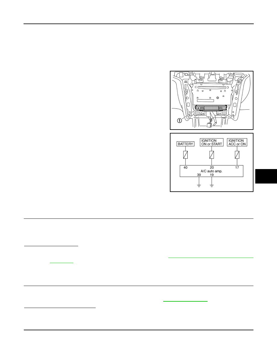
A/C Auto Amp. (Air Conditioner Automatic Amplifier)
The A/C auto amp. (1) has a built-in microcomputer that processes
information sent from various sensors needed for air conditioner
operation. The air mix door motor(s), the mode door motor, the
intake door motor, the upper ventilator door motor, the blower motor
and the compressor are then controlled.
When the various switches and temperature control dial are oper-
ated, data is input to the A/C auto amp. from the AV control unit
using CAN communication.
The A/C auto amp. is operated with control mechanisms. Signals
from various switches and Potentio Temperature Control (PTC) are
directly entered into the A/C auto amp.
Power Supply and Ground Circuit for A/C Auto Amp.
A/C AUTO AMP. : Component Function Check
INFOID:0000000005514745
1.
CHECK OPERATION
1.
Press the AUTO switch, and then check that “AUTO” is shown on the display.
2.
Operate the temperature control dial (driver side). Check that the fan speed or outlet changes. (The dis-
charge air temperature or fan speed varies depending on the ambient temperature, in-vehicle tempera-
ture, and temperature setting.)
Does it operate normally?
YES
>> INSPECTION END
NO
>> Perform trouble diagnosis for the A/C system. Refer to
HAC-197, "A/C AUTO AMP. : Diagnosis
.
A/C AUTO AMP. : Diagnosis Procedure
INFOID:0000000005514746
1.
INSPECTION BY FAIL-SAFE FUNCTION
1.
Turn the ignition switch ON.
2.
After approximately 30 seconds, check that the air conditioner is operated by the fail-safe function (the
operation display of air conditioner is not performed). Refer to
.
Is the fail-safe function operated?
YES
>> GO TO 5.
NO
>> GO TO 2.
2.
CHECK A/C AUTO AMP. POWER SUPPLY CIRCUIT
1.
Disconnect the A/C auto amp. connector.
2.
Check voltage between A/C auto amp. harness connector and ground.
JPIIA0609ZZ
JPIIA0617GB
HAC-198
< DTC/CIRCUIT DIAGNOSIS >
[WITH 7 INCH DISPLAY]
POWER SUPPLY AND GROUND CIRCUIT
Is the inspection result normal?
YES
>> GO TO 4.
NO
>> GO TO 3.
3.
CHECK FUSE
Check 10A fuses [Nos. 3, 6 and 19, located in the fuse block (J/B)].
NOTE:
Refer to
PG-113, "Fuse, Connector and Terminal Arrangement"
Is the inspection result normal?
YES
>> Repair the harnesses or connectors.
NO
>> Replace the fuse after repairing the applicable circuit.
4.
CHECK A/C AUTO AMP. CIRCUIT CONTINUITY
1.
Turn ignition switch OFF.
2.
Check continuity between A/C auto amp. harness connector and ground.
Is the inspection result normal?
YES
>> GO TO 5.
NO
>> Repair the harnesses or connectors.
5.
CHECK PRESET SWITCH
Check the preset switch. Refer to
(bose audio without navigation) or
(bose audio with navigation).
Is the inspection result normal?
YES
>> Replace the A/C auto amp.
NO
>> Repair or replace parts according to the inspection results.
(+)
(
−
)
Voltage
A/C auto amp.
—
Ignition switch position
Connector
Terminal
OFF
ACC
ON
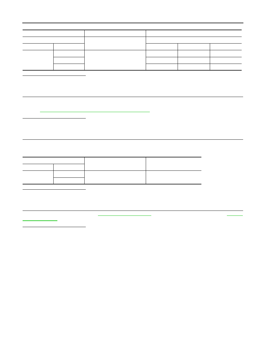
M50
17
Ground
Approx. 0 V
Battery voltage
Battery voltage
20
Approx. 0 V
Approx. 0 V
Battery voltage
40
Battery voltage
Battery voltage
Battery voltage
A/C auto amp.
—
Continuity
Connector
Terminal
M50
19
Ground
Existed
39
Нет комментариевНе стесняйтесь поделиться с нами вашим ценным мнением.
Текст