Nissan Murano Z51. Instruction — part 979
LAN-122
< DTC/CIRCUIT DIAGNOSIS >
[CAN SYSTEM (TYPE 4)]
ABS BRANCH LINE CIRCUIT
ABS BRANCH LINE CIRCUIT
Diagnosis Procedure
INFOID:0000000005595417
1.
CHECK CONNECTOR
1.
Turn the ignition switch OFF.
2.
Disconnect the battery cable from the negative terminal.
3.
Check the terminals and connectors of the ABS actuator and electric unit (control unit) for damage, bend
and loose connection (unit side and connector side).
Is the inspection result normal?
YES
>> GO TO 2.
NO
>> Repair the terminal and connector.
2.
CHECK HARNESS FOR OPEN CIRCUIT
1.
Disconnect the connector of ABS actuator and electric unit (control unit).
2.
Check the resistance between the ABS actuator and electric unit (control unit) harness connector termi-
nals.
Is the measurement value within the specification?
YES
>> GO TO 3.
NO
>> Repair the ABS actuator and electric unit (control unit) branch line.
3.
CHECK POWER SUPPLY AND GROUND CIRCUIT
Check the power supply and the ground circuit of the ABS actuator and electric unit (control unit). Refer to
Is the inspection result normal?
YES (Present error)>>Replace the ABS actuator and electric unit (control unit). Refer to
.
YES (Past error)>>Error was detected in the ABS actuator and electric unit (control unit) branch line.
NO
>> Repair the power supply and the ground circuit.
ABS actuator and electric unit (control unit) harness connector
Resistance (
Ω
)
Connector No.
Terminal No.
E36
23
21
Approx. 54 – 66
LAN
TCM BRANCH LINE CIRCUIT
LAN-123
< DTC/CIRCUIT DIAGNOSIS >
[CAN SYSTEM (TYPE 4)]
C
D
E
F
G
H
I
J
K
L
B
A
O
P
N
TCM BRANCH LINE CIRCUIT
Diagnosis Procedure
INFOID:0000000005595418
1.
CHECK CONNECTOR
1.
Turn the ignition switch OFF.
2.
Disconnect the battery cable from the negative terminal.
3.
Check the following terminals and connectors for damage, bend and loose connection (unit side and con-
nector side).
-
TCM
-
Harness connector F123
-
Harness connector E6
Is the inspection result normal?
YES
>> GO TO 2.
NO
>> Repair the terminal and connector.
2.
CHECK HARNESS FOR OPEN CIRCUIT
1.
Disconnect the connector of TCM.
2.
Check the resistance between the TCM harness connector terminals.
Is the measurement value within the specification?
YES
>> GO TO 3.
NO
>> Repair the TCM branch line.
3.
CHECK POWER SUPPLY AND GROUND CIRCUIT
Check the power supply and the ground circuit of the TCM. Refer to
Is the inspection result normal?
YES (Present error)>>Replace the TCM. Refer to
TM-160, "Removal and Installation"
YES (Past error)>>Error was detected in the TCM branch line.
NO
>> Repair the power supply and the ground circuit.
TCM harness connector
Resistance (
Ω
)
Connector No.
Terminal No.
F23
32
31
Approx. 54 – 66
LAN-124
< DTC/CIRCUIT DIAGNOSIS >
[CAN SYSTEM (TYPE 4)]
IPDM-E BRANCH LINE CIRCUIT
IPDM-E BRANCH LINE CIRCUIT
Diagnosis Procedure
INFOID:0000000005595419
1.
CHECK CONNECTOR
1.
Turn the ignition switch OFF.
2.
Disconnect the battery cable from the negative terminal.
3.
Check the terminals and connectors of the IPDM E/R for damage, bend and loose connection (unit side
and connector side).
Is the inspection result normal?
YES
>> GO TO 2.
NO
>> Repair the terminal and connector.
2.
CHECK HARNESS FOR OPEN CIRCUIT
1.
Disconnect the connector of IPDM E/R.
2.
Check the resistance between the IPDM E/R harness connector terminals.
Is the measurement value within the specification?
YES
>> GO TO 3.
NO
>> Repair the IPDM E/R branch line.
3.
CHECK POWER SUPPLY AND GROUND CIRCUIT
Check the power supply and the ground circuit of the IPDM E/R. Refer to
Is the inspection result normal?
YES (Present error)>>Replace the IPDM E/R. Refer to
PCS-35, "Removal and Installation"
YES (Past error)>>Error was detected in the IPDM E/R branch line.
NO
>> Repair the power supply and the ground circuit.
IPDM E/R harness connector
Resistance (
Ω
)
Connector No.
Terminal No.
E11
40
39
Approx. 108 – 132
LAN
CAN COMMUNICATION CIRCUIT
LAN-125
< DTC/CIRCUIT DIAGNOSIS >
[CAN SYSTEM (TYPE 4)]
C
D
E
F
G
H
I
J
K
L
B
A
O
P
N
CAN COMMUNICATION CIRCUIT
Diagnosis Procedure
INFOID:0000000005595420
1.
CONNECTOR INSPECTION
1.
Turn the ignition switch OFF.
2.
Disconnect the battery cable from the negative terminal.
3.
Disconnect all the unit connectors on CAN communication system.
4.
Check terminals and connectors for damage, bend and loose connection.
Is the inspection result normal?
YES
>> GO TO 2.
NO
>> Repair the terminal and connector.
2.
CHECK HARNESS CONTINUITY (SHORT CIRCUIT)
Check the continuity between the data link connector terminals.
Is the inspection result normal?
YES
>> GO TO 3.
NO
>> Check the harness and repair the root cause.
3.
CHECK HARNESS CONTINUITY (SHORT CIRCUIT)
Check the continuity between the data link connector and the ground.
Is the inspection result normal?
YES
>> GO TO 4.
NO
>> Check the harness and repair the root cause.
4.
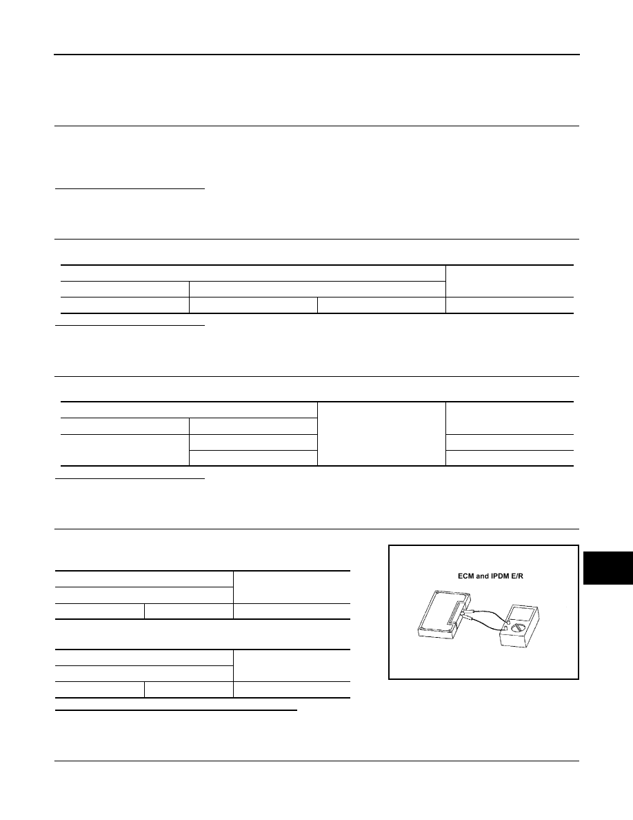
CHECK ECM AND IPDM E/R TERMINATION CIRCUIT
1.
Remove the ECM and the IPDM E/R.
2.
Check the resistance between the ECM terminals.
3.
Check the resistance between the IPDM E/R terminals.
Is the measurement value within the specification?
YES
>> GO TO 5.
NO
>> Replace the ECM and/or the IPDM E/R.
5.
CHECK SYMPTOM
Connect all the connectors. Check if the symptoms described in the “Symptom (Results from interview with
customer)” are reproduced.
Data link connector
Continuity
Connector No.
Terminal No.
M4
6
14
Not existed
Data link connector
Ground
Continuity
Connector No.
Terminal No.
M4
6
Not existed
14
Not existed
ECM
Resistance (
Ω
)
Terminal No.
98
97
Approx. 108 – 132
IPDM E/R
Resistance (
Ω
)
Terminal No.
40
39
Approx. 108 – 132
LKIA0037E
Нет комментариевНе стесняйтесь поделиться с нами вашим ценным мнением.
Текст