Nissan Murano Z51. Instruction — part 1431
P0840 TRANSMISSION FLUID PRESSURE SEN/SW A
TM-75
< DTC/CIRCUIT DIAGNOSIS >
[CVT: RE0F09B]
C
E
F
G
H
I
J
K
L
M
A
B
TM
N
O
P
YES
>> GO TO 3.
NO
>> GO TO 5.
3.
CHECK HARNESS BETWEEN TCM AND CVT UNIT (SECONDARY PRESSURE SENSOR) (PART 1)
1.
Turn ignition switch OFF.
2.
Disconnect TCM connector and CVT unit connector.
3.
Check continuity between TCM vehicle side harness connector terminal and CVT unit vehicle side har-
ness connector terminal.
Is the inspection result normal?
YES
>> GO TO 4.
NO
>> Repair or replace damaged parts.
4.
CHECK HARNESS BETWEEN TCM AND CVT UNIT (SECONDARY PRESSURE SENSOR) (PART 2)
Check continuity between TCM vehicle side harness connector terminal and ground.
Is the inspection result normal?
YES
>> GO TO 7.
NO
>> Repair or replace damaged parts.
5.
CHECK HARNESS BETWEEN TCM AND CVT UNIT (SENSOR POWER AND SENSOR GROUND) (PART
1)
1.
Turn ignition switch OFF.
2.
Disconnect TCM connector and CVT unit connector.
3.
Check continuity between TCM vehicle side harness connector terminals and CVT unit vehicle side har-
ness connector terminals.
Is the inspection result normal?
YES
>> GO TO 6.
NO
>> Repair or replace damaged parts.
6.
CHECK HARNESS BETWEEN TCM AND CVT UNIT (SENSOR POWER AND SENSOR GROUND) (PART
2)
Check continuity between TCM vehicle side harness connector terminals and ground.
Is the inspection result normal?
YES
>> GO TO 7.
NO
>> Repair or replace damaged parts.
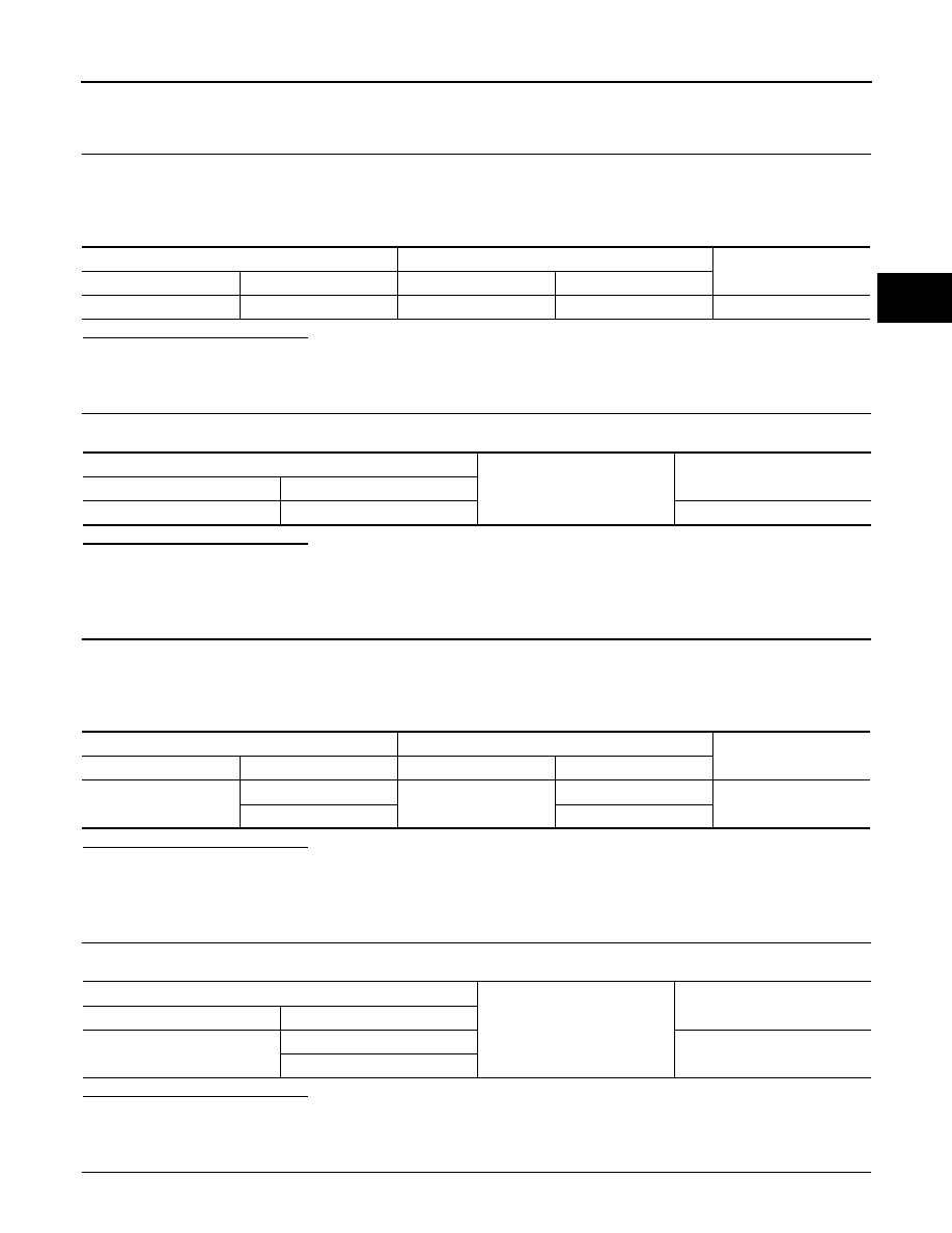
7.
CHECK TCM
TCM vehicle side harness connector
CVT unit vehicle side harness connector
Continuity
Connector
Terminal
Connector
Terminal
F23
15
F24
23
Existed
TCM vehicle side harness connector
Ground
Continuity
Connector
Terminal
F23
15
Not existed
TCM vehicle side harness connector
CVT unit vehicle side harness connector
Continuity
Connector
Terminal
Connector
Terminal
F23
25
F24
19
Existed
26
20
TCM vehicle side harness connector
Ground
Continuity
Connector
Terminal
F23
25
Not existed
26

TM-76
< DTC/CIRCUIT DIAGNOSIS >
[CVT: RE0F09B]
P0840 TRANSMISSION FLUID PRESSURE SEN/SW A
1.
Replace with the same type of TCM. Refer to
.
2.
Connect each connector.
3.
Perform “DTC CONFIRMATION PROCEDURE”. Refer to
.
Is “P0840” detected?
YES
>> Replace transaxle assembly. Refer to
NO
8.
DETECT MALFUNCTIONING ITEMS
Check TCM connector pin terminals for damage or loose connection with harness connector.
Is the inspection result normal?
YES
NO
>> Repair or replace damaged parts.
P0841 TRANSMISSION FLUID PRESSURE SEN/SW A
TM-77
< DTC/CIRCUIT DIAGNOSIS >
[CVT: RE0F09B]
C
E
F
G
H
I
J
K
L
M
A
B
TM
N
O
P
P0841 TRANSMISSION FLUID PRESSURE SEN/SW A
Description
INFOID:0000000005514021
Using the engine load (throttle position), the primary pulley revolution speed, and the secondary pulley revolu-
tion speed as input signals, TCM changes the operating pressure of the primary pulley and the secondary pul-
ley and changes the groove width of the pulley to control the gear ratio.
DTC Logic
INFOID:0000000005514022
DTC DETECTION LOGIC
DTC CONFIRMATION PROCEDURE
CAUTION:
Always drive vehicle at a safe speed.
NOTE:
Immediately after performing any “DTC CONFIRMATION PROCEDURE”, always turn ignition switch OFF.
Then wait at least 10 seconds before performing the next test.
1.
CHECK DTC DETECTION
With CONSULT-III
1.
Turn ignition switch ON.
2.
Select “Data Monitor” in “TRANSMISSION”.
3.
Start engine and maintain the following conditions for at least 12 consecutive seconds.
Is “P0841” detected?
YES
>> Go to
NO
>> Check intermittent incident. Refer to
GI-39, "Intermittent Incident"
.
Diagnosis Procedure
INFOID:0000000005514023
1.
CHECK LINE PRESSURE
Perform line pressure test. Refer to
TM-153, "Inspection and Judgment"
.
Is the inspection result normal?
YES
>> .GO TO 2.
NO
>> Repair or replace damaged parts. Refer to
TM-153, "Inspection and Judgment"
.
2.
CHECK SECONDARY PRESSURE SENSOR SYSTEM
Check secondary pressure sensor system. Refer to
Is the inspection result normal?
YES
>> GO TO 3.
NO
>> Repair or replace damaged parts.
3.
CHECK PRIMARY PRESSURE SENSOR SYSTEM
Check primary pressure sensor system. Refer to
Is the inspection result normal?
YES
>> GO TO 4.
NO
>> Repair or replace damaged parts.
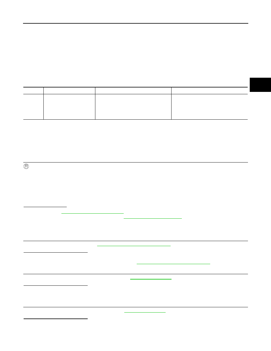
DTC
Trouble diagnosis name
DTC is detected if...
Possible cause
P0841
Transmission Fluid Pressure
Sensor/Switch A Circuit
Range/Performance
Correlation between the values of the trans-
mission fluid pressure sensor A (secondary
pressure sensor) and the transmission fluid
pressure sensor B (primary pressure sen-
sor) is out of specification.
• Harness or connectors
(Sensor circuit is open or shorted.)
• Secondary pressure sensor
• Primary pressure sensor
VEHICLE SPEED
: 40 km/h (25 MPH) or more
RANGE
: “D” position
TM-78
< DTC/CIRCUIT DIAGNOSIS >
[CVT: RE0F09B]
P0841 TRANSMISSION FLUID PRESSURE SEN/SW A
4.
CHECK LINE PRESSURE SOLENOID VALVE
1.
Turn ignition switch OFF.
2.
Disconnect CVT unit connector.
3.
Check line pressure solenoid valve. Refer to
TM-78, "Component Inspection (Line Pressure Solenoid
Is the inspection result normal?
YES
>> GO TO 5.
NO
>> Repair or replace damaged parts.
5.
CHECK SECONDARY PRESSURE SOLENOID VALVE
Check secondary pressure solenoid valve. Refer to
TM-78, "Component Inspection (Secondary Pressure
Is the inspection result normal?
YES
>> GO TO 6.
NO
>> Repair or replace damaged parts.
6.
CHECK STEP MOTOR SYSTEM
Check step motor system. Refer to
Is the inspection result normal?
YES
>> GO TO 7.
NO
>> Repair or replace damaged parts.
7.
DETECT MALFUNCTIONING ITEMS
Check TCM connector pin terminals for damage or loose connection with harness connector.
Is the inspection result normal?
YES
NO
>> Repair or replace damaged parts.
Component Inspection (Line Pressure Solenoid Valve)
INFOID:0000000005514024
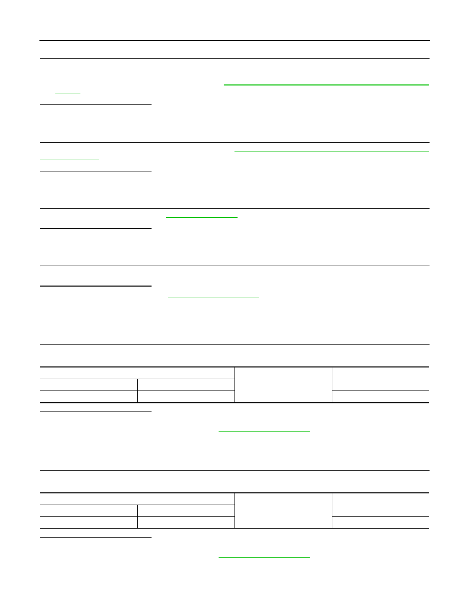
1.
CHECK LINE PRESSURE SOLENOID VALVE
Check resistance between CVT unit connector terminal and ground.
Is the inspection result normal?
YES
>> INSPECTION END
NO
>> Replace transaxle assembly. Refer to
Component Inspection (Secondary Pressure Solenoid Valve)
INFOID:0000000005514025
1.
CHECK SECONDARY PRESSURE SOLENOID VALVE
Check resistance between CVT unit connector terminal and ground.
Is the inspection result normal?
YES
>> INSPECTION END
NO
>> Replace transaxle assembly. Refer to
CVT unit connector
Ground
Resistance (Approx.)
Connector
Terminal
F24
2
3.0 – 9.0
Ω
CVT unit connector
Ground
Resistance (Approx.)
Connector
Terminal
F24
3
3.0 – 9.0
Ω
Нет комментариевНе стесняйтесь поделиться с нами вашим ценным мнением.
Текст