Nissan Murano Z51. Instruction — part 473
DLN-26
< DTC/CIRCUIT DIAGNOSIS >
[TRANSFER: TY20A]
AWD LOCK INDICATOR LAMP
AWD LOCK INDICATOR LAMP
Description
INFOID:0000000005514180
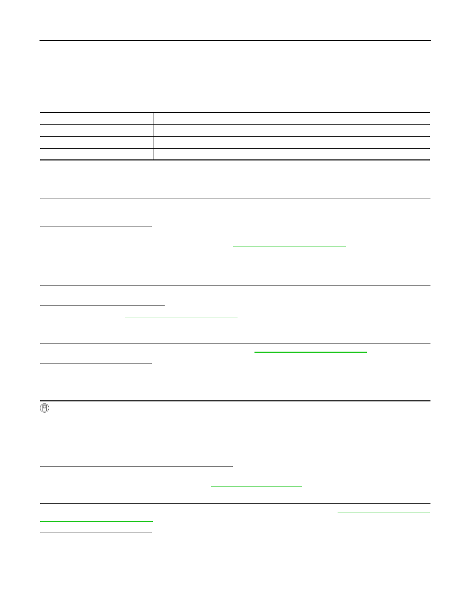
The following is the indications of indicator lamp after the engine start.
AWD LOCK INDICATOR LAMP
Component Function Check
INFOID:0000000005514181
1.
AWD LOCK INDICATOR LAMP OPERATION CHECK 1
Check that AWD LOCK indicator lamp turns on for approximately 1 second after the ignition switch is turned
ON.
Is the inspection result normal?
YES
>> INSPECTION END
NO
>> Proceed to diagnosis procedure. Refer to
Diagnosis Procedure
INFOID:0000000005514182
1.
CHECK AWD WARNING LAMP
Start the engine and drive at 30 km/h (19 MPH) or more for approximately 1 minute.
Does AWD warning lamp turn ON?
YES
>> Proceed to
.
NO
>> GO TO 2.
2.
CHECK AWD LOCK SWITCH
Perform the trouble diagnosis for AWD lock switch. Refer to
.
Is the inspection result normal?
YES
>> GO TO 3.
NO
>> Repair or replace the error-detected parts.
3.
CHECK AWD LOCK INDICATOR LAMP SIGNAL
With CONSULT-III
1.
Start the engine.
CAUTION:
Stop the vehicle.
2.
Change AWD lock switch to “LOCK” from “AUTO”.
3.
Check “4WD MODE MON” of CONSULT-III “DATA MONITOR” for “ALL MODE AWD/4WD”.
Does the item on “DATA MONITOR” indicate “LOCK”?
YES
>> GO TO 4.
NO
>> Replace AWD control unit. Refer to
4.
CHECK COMBINATION METER POWER SUPPLY CIRCUIT
Perform the trouble diagnosis for combination meter power supply circuit. Refer to
Is the inspection result normal?
YES
>> INSPECTION END
NO
>> Repair or replace the error-detected parts.
Condition
AWD LOCK indicator lamp
Lamp check
Turns ON for approx. 1 second when ignition switch is turned ON.
AUTO mode
OFF
LOCK mode
ON
AWD CONTROL UNIT
DLN-27
< ECU DIAGNOSIS INFORMATION >
[TRANSFER: TY20A]
C
E
F
G
H
I
J
K
L
M
A
B
DLN
N
O
P
ECU DIAGNOSIS INFORMATION
AWD CONTROL UNIT
Reference Value
INFOID:0000000005514183
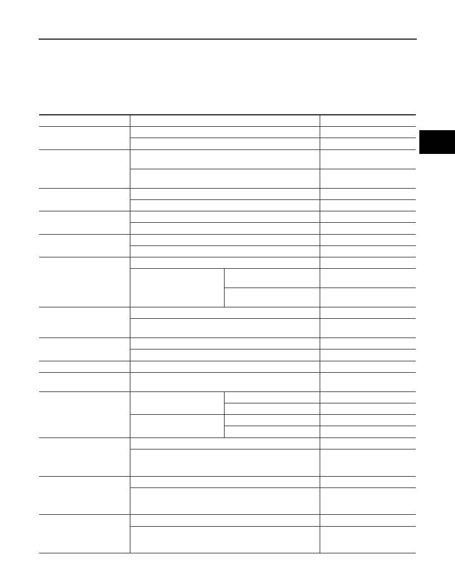
VALUES ON THE DIAGNOSIS TOOL
Monitor item
Condition
Value/Status
STOP LAMP SW
Brake pedal: Depressed
On
Brake pedal: Released
Off
ENG SPEED SIG
Engine stopped
(Engine speed: Less than 400 rpm)
Stop
Engine running
(Engine speed: 400 rpm or more)
Run
ETS ACTUATOR
Engine stopped (Ignition switch: ON)
Off
Engine running
On
4WD WARN LAMP
AWD warning lamp: ON
On
AWD warning lamp: OFF
Off
4WD MODE SW
Releasing AWD lock switch.
AUTO
AWD lock switch is hold pressed.
LOCK
4WD MODE MON
AWD LOCK indicator lamp: OFF
AUTO
AWD LOCK indicator lamp: ON
Vehicle speed below 10 km/h (6
mph)
LOCK
Vehicle speed above 10 km/h (6
mph)
AUTO
DIS-TIRE MONI
Vehicle running with normal size tire installed
0 – 4 mm
Vehicle running with improper size tire installed (Front/rear tire size
difference, wear condition)
4 – 8 mm, 8 – mm
P BRAKE SW
Parking brake operated
On
Parking brake not operated
Off
BATTERY VOLT
Always
Battery voltage
THRTL POS SEN
When depressing accelerator pedal
(Value rises gradually in response to throttle position.)
0 – 100%
ETS SOLENOID
Engine running
• At idle speed
AWD LOCK indicator lamp: OFF
Approx. 0.000 A
AWD LOCK indicator lamp: ON
Approx. 0.000 A
Engine running
• 3,000 rpm or more constant
AWD LOCK indicator lamp: OFF
Approx. 0.000 – 1.800 A*
AWD LOCK indicator lamp: ON
Approx. 1.800 A
FR RH SENSOR
Vehicle stopped
0.00 km/h (0.00 mph)
Vehicle running
CAUTION:
Check air pressure of tire under standard condition.
Nearly matches the speed meter
display (
±
10% or less)
FR LH SENSOR
Vehicle stopped
0.00 km/h (0.00 mph)
Vehicle running
CAUTION:
Check air pressure of tire under standard condition.
Nearly matches the speed meter
display(
±
10% or less)
RR RH SENSOR
Vehicle stopped
0.00 km/h (0.00 mph)
Vehicle running
CAUTION:
Check air pressure of tire under standard condition.
Nearly matches the speed meter
display(
±
10% or less)
DLN-28
< ECU DIAGNOSIS INFORMATION >
[TRANSFER: TY20A]
AWD CONTROL UNIT
*: The values are changed by throttle opening and engine speed.
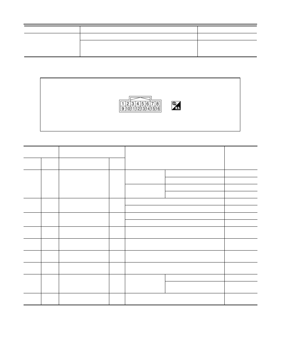
TERMINAL LAYOUT
PHYSICAL VALUES
*: The values are changed by throttle opening and engine speed.
CAUTION:
When using circuit tester to measure voltage for inspection, be sure not to extend forcibly any connector terminals.
RR LH SENSOR
Vehicle stopped
0.00 km/h (0.00 mph)
Vehicle running
CAUTION:
Check air pressure of tire under standard condition.
Nearly matches the speed meter
display(
±
10%)
Monitor item
Condition
Value/Status
JSDIA0057ZZ
Terminal No.
(Wire color)
Description
Condition
Value (Approx.)
+
-
Signal name
Input/
Output
1
(LG)
Ground
AWD solenoid power sup-
ply
Output
Engine speed: At idle
AWD LOCK indicator lamp: OFF
0 V
AWD LOCK indicator lamp: ON
0 V
Engine speed: 3,000
rpm or more constant
AWD LOCK indicator lamp: OFF
2.5 V*
AWD LOCK indicator lamp: ON
8 V
2
(L)
Ground
AWD solenoid ground
—
Engine speed: At idle
0 V
Engine speed: 3,000 rpm or more constant
0 V
7
(R)
Ground
Ignition switch
Input
Ignition switch: ON
Battery voltage
Ignition switch: OFF
0 V
8
(L)
—
CAN-H
Input/
Output
—
—
9
(G)
Ground
Power supply (AWD sole-
noid)
Input
Always
Battery voltage
10
(B)
Ground
Ground
—
Always
0 V
11
(B)
Ground
Ground
—
Always
0 V
14
(Y)
Ground
AWD lock switch
Output
Ignition switch: ON
Releasing AWD lock switch
Battery voltage
AWD lock switch is hold
pressed.
0 V
16
(P)
—
CAN-L
Input/
Output
—
—
AWD CONTROL UNIT
DLN-29
< ECU DIAGNOSIS INFORMATION >
[TRANSFER: TY20A]
C
E
F
G
H
I
J
K
L
M
A
B
DLN
N
O
P
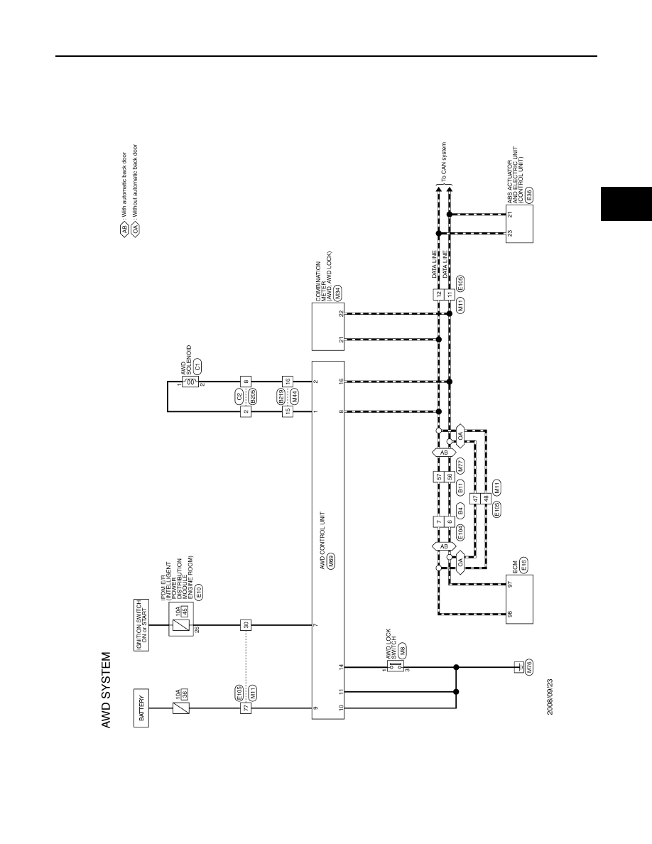
Wiring Diagram - AWD SYSTEM -
INFOID:0000000005514184
JCDWM0487GB
Нет комментариевНе стесняйтесь поделиться с нами вашим ценным мнением.
Текст