Nissan Murano Z51. Instruction — part 989
LAN-162
< DTC/CIRCUIT DIAGNOSIS >
[CAN SYSTEM (TYPE 7)]
PWBD BRANCH LINE CIRCUIT
PWBD BRANCH LINE CIRCUIT
Diagnosis Procedure
INFOID:0000000005595472
1.
CHECK CONNECTOR
1.
Turn the ignition switch OFF.
2.
Disconnect the battery cable from the negative terminal.
3.
Check the terminals and connectors of the automatic back door control unit for damage, bend and loose
connection (unit side and connector side).
Is the inspection result normal?
YES
>> GO TO 2.
NO
>> Repair the terminal and connector.
2.
CHECK HARNESS FOR OPEN CIRCUIT
1.
Disconnect the connector of automatic back door control unit.
2.
Check the resistance between the automatic back door control unit harness connector terminals.
Is the measurement value within the specification?
YES
>> GO TO 3.
NO
>> Repair the automatic back door control unit branch line.
3.
CHECK POWER SUPPLY AND GROUND CIRCUIT
Check the power supply and the ground circuit of the automatic back door control unit. Refer to
"AUTOMATIC BACK DOOR CONTROL UNIT : Diagnosis Procedure"
Is the inspection result normal?
YES (Present error)>>Replace the automatic back door control unit. Refer to
.
YES (Past error)>>Error was detected in the automatic back door control unit branch line.
NO
>> Repair the power supply and the ground circuit.
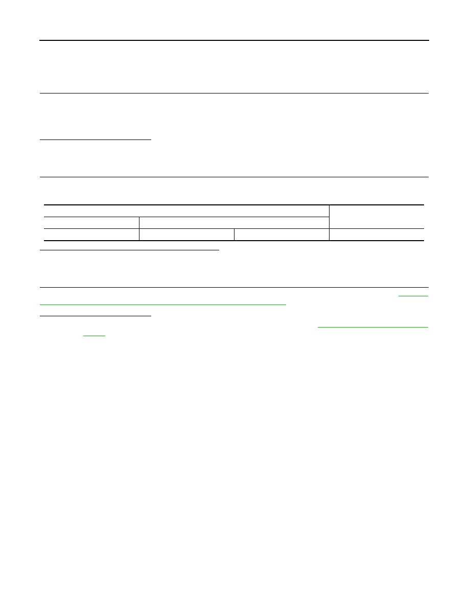
Automatic back door control unit harness connector
Resistance (
Ω
)
Connector No.
Terminal No.
B8
6
7
Approx. 54 – 66
LAN
4WD BRANCH LINE CIRCUIT
LAN-163
< DTC/CIRCUIT DIAGNOSIS >
[CAN SYSTEM (TYPE 7)]
C
D
E
F
G
H
I
J
K
L
B
A
O
P
N
4WD BRANCH LINE CIRCUIT
Diagnosis Procedure
INFOID:0000000005595473
1.
CHECK CONNECTOR
1.
Turn the ignition switch OFF.
2.
Disconnect the battery cable from the negative terminal.
3.
Check the terminals and connectors of the AWD control unit for damage, bend and loose connection (unit
side and connector side).
Is the inspection result normal?
YES
>> GO TO 2.
NO
>> Repair the terminal and connector.
2.
CHECK HARNESS FOR OPEN CIRCUIT
1.
Disconnect the connector of AWD control unit.
2.
Check the resistance between the AWD control unit harness connector terminals.
Is the measurement value within the specification?
YES
>> GO TO 3.
NO
>> Repair the AWD control unit branch line.
3.
CHECK POWER SUPPLY AND GROUND CIRCUIT
Check the power supply and the ground circuit of the AWD control unit. Refer to
.
Is the inspection result normal?
YES (Present error)>>Replace the AWD control unit. Refer to
DLN-50, "Removal and Installation"
YES (Past error)>>Error was detected in the AWD control unit branch line.
NO
>> Repair the power supply and the ground circuit.
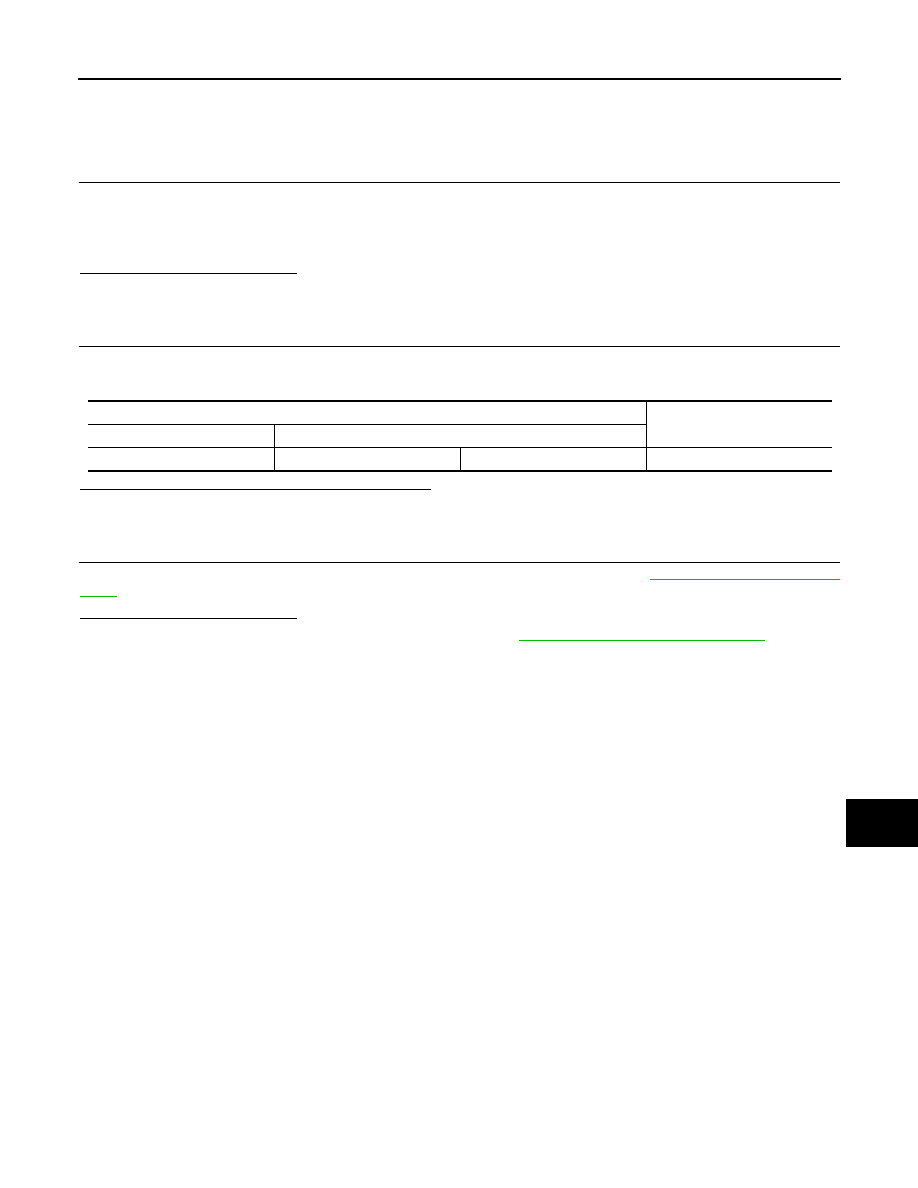
AWD control unit harness connector
Resistance (
Ω
)
Connector No.
Terminal No.
M69
8
16
Approx. 54 – 66
LAN-164
< DTC/CIRCUIT DIAGNOSIS >
[CAN SYSTEM (TYPE 7)]
AV BRANCH LINE CIRCUIT
AV BRANCH LINE CIRCUIT
Diagnosis Procedure
INFOID:0000000005595474
1.
CHECK CONNECTOR
1.
Turn the ignition switch OFF.
2.
Disconnect the battery cable from the negative terminal.
3.
Check the terminals and connectors of the AV control unit for damage, bend and loose connection (unit
side and connector side).
Is the inspection result normal?
YES
>> GO TO 2.
NO
>> Repair the terminal and connector.
2.
CHECK HARNESS FOR OPEN CIRCUIT
1.
Disconnect the connector of AV control unit.
2.
Check the resistance between the AV control unit harness connector terminals.
-
Models with navigation system
-
Models without navigation system
Is the measurement value within the specification?
YES
>> GO TO 3.
NO
>> Repair the AV control unit branch line.
3.
CHECK POWER SUPPLY AND GROUND CIRCUIT
Check the power supply and the ground circuit of the AV control unit. Refer to the following.
• BOSE audio without navigation:
AV-107, "AV CONTROL UNIT : Diagnosis Procedure"
• BOSE audio with navigation:
AV-631, "AV CONTROL UNIT : Diagnosis Procedure"
Is the inspection result normal?
YES (Present error)>>Replace the AV control unit. Refer to the following.
• BOSE audio without navigation:
AV-534, "Removal and Installation"
AV-787, "Removal and Installation"
YES (Past error)>>Error was detected in the AV control unit branch line.
NO
>> Repair the power supply and the ground circuit.
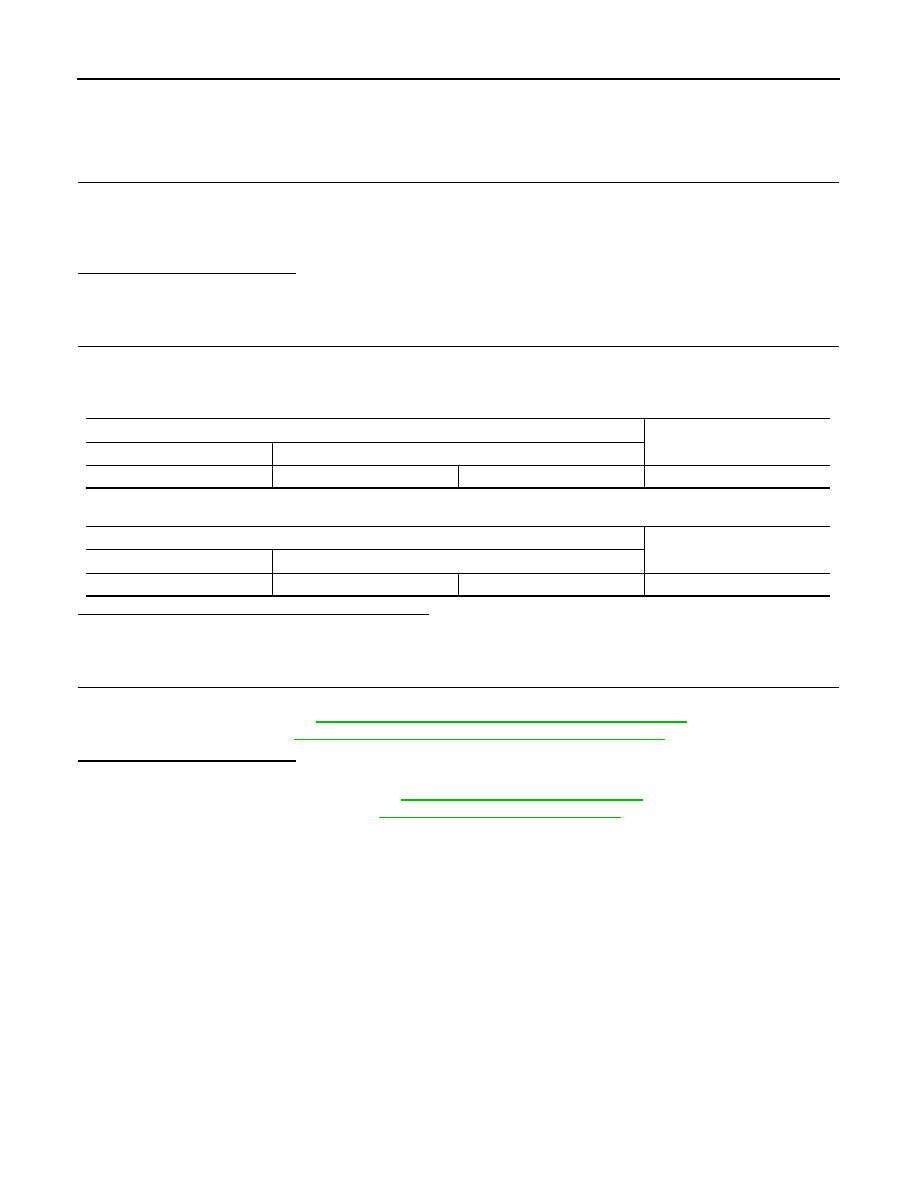
AV control unit harness connector
Resistance (
Ω
)
Connector No.
Terminal No.
M145
52
53
Approx. 54 – 66
AV control unit harness connector
Resistance (
Ω
)
Connector No.
Terminal No.
M131
86
87
Approx. 54 – 66
LAN
HVAC BRANCH LINE CIRCUIT
LAN-165
< DTC/CIRCUIT DIAGNOSIS >
[CAN SYSTEM (TYPE 7)]
C
D
E
F
G
H
I
J
K
L
B
A
O
P
N
HVAC BRANCH LINE CIRCUIT
Diagnosis Procedure
INFOID:0000000005595475
1.
CHECK CONNECTOR
1.
Turn the ignition switch OFF.
2.
Disconnect the battery cable from the negative terminal.
3.
Check the terminals and connectors of the A/C auto amp. for damage, bend and loose connection (unit
side and connector side).
Is the inspection result normal?
YES
>> GO TO 2.
NO
>> Repair the terminal and connector.
2.
CHECK HARNESS FOR OPEN CIRCUIT
1.
Disconnect the connector of A/C auto amp.
2.
Check the resistance between the A/C auto amp. harness connector terminals.
Is the measurement value within the specification?
YES
>> GO TO 3.
NO
>> Repair the A/C auto amp. branch line.
3.
CHECK POWER SUPPLY AND GROUND CIRCUIT
Check the power supply and the ground circuit of the A/C auto amp. Refer to the following.
• Without 7 inch display:
HAC-76, "A/C AUTO AMP. : Diagnosis Procedure"
• With 7 inch display:
HAC-197, "A/C AUTO AMP. : Diagnosis Procedure"
Is the inspection result normal?
YES (Present error)>>Replace the A/C auto amp. Refer to the following.
• Without 7 inch display:
VTL-25, "Removal and Installation"
• With 7 inch display:
VTL-87, "Removal and Installation"
YES (Past error)>>Error was detected in the A/C auto amp. branch line.
NO
>> Repair the power supply and the ground circuit.
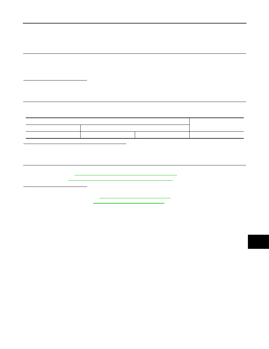
A/C auto amp. harness connector
Resistance (
Ω
)
Connector No.
Terminal No.
M50
1
2
Approx. 54 – 66
Нет комментариевНе стесняйтесь поделиться с нами вашим ценным мнением.
Текст