Nissan Murano Z51. Instruction — part 412
DLK-156
< DTC/CIRCUIT DIAGNOSIS >
[WITH INTELLIGENT KEY SYSTEM]
TOUCH SENSOR
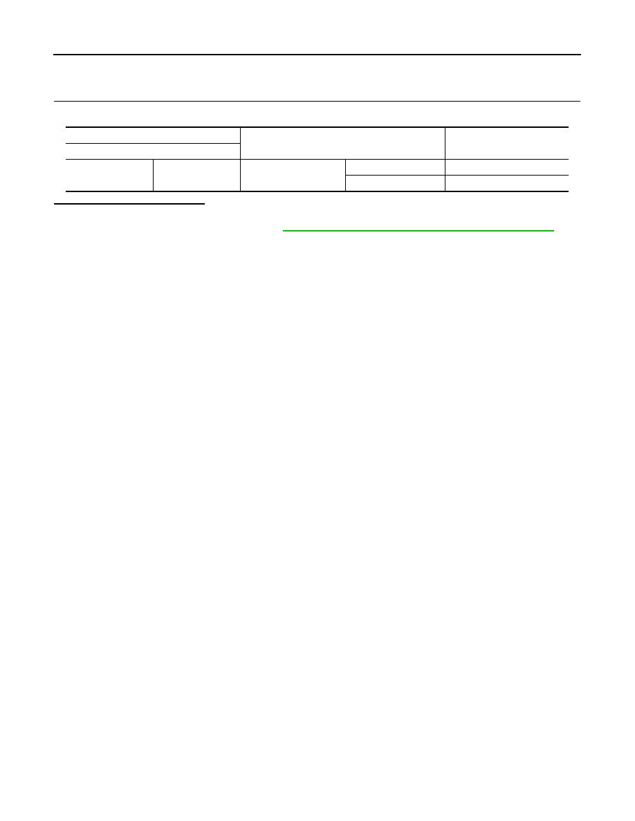
LH : Component Inspection
INFOID:0000000005517653
1.
CHECK TOUCH SENSOR LH
Check touch sensor LH.
Is the inspection result normal?
YES
>> INSPECTION END
NO
>> Replace touch sensor LH. Refer to
DLK-356, "TOUCH SENSOR : Removal and Installation"
.
Terminal
Condition
Resistance
(Approx.)
Touch sensor LH
1
2
Touch sensor LH
Detect obstruction
120
Ω
or less
Other than above
1 k
Ω
±
10%
ENCODER
DLK-157
< DTC/CIRCUIT DIAGNOSIS >
[WITH INTELLIGENT KEY SYSTEM]
C
D
E
F
G
H
I
J
L
M
A
B
DLK
N
O
P
ENCODER
Description
INFOID:0000000005517654
The automatic back door control unit receives the pulse signals from encoders A and B that occurred due to
synchronization with the back door operation. The automatic back door control unit calculates the back door
position, operation direction, and operation speed according to the received pulse signals.
Component Function Check
INFOID:0000000005517655
1.
CHECK FUNCTION
Check encoder (“ENCODER A”, “ENCODER B”) in Data Monitor mode.
Is the inspection result normal?
YES
>> Encoder is OK.
NO
>> Refer to
DLK-157, "Diagnosis Procedure"
Diagnosis Procedure
INFOID:0000000005517656
1.
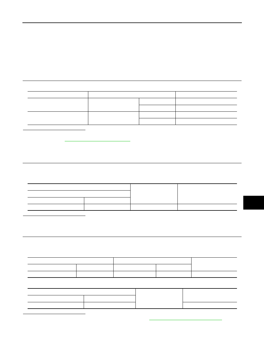
CHECK ENCODER POWER SUPPLY
1.
Turn ignition switch OFF.
2.
Disconnect automatic back door unit connector.
3.
Check voltage between automatic back door unit harness connector and ground.
Is the inspection result normal?
YES
>> GO TO 3.
NO
>> GO TO 2.
2.
CHECK ENCODER POWER SUPPLY CIRCUIT
1.
Disconnect automatic back door control unit connector.
2.
Check continuity between automatic back door control unit harness connector and automatic back door
unit harness connector.
3.
Check continuity between automatic back door control unit harness connector and ground.
Is the inspection result normal?
YES
>> Replace automatic back door control unit. Refer to
DLK-370, "Removal and Installation"
.
NO
>> Repair or replace harness.
Monitor item
Condition
Status
ENCODER A
Back door
Moving
Change HI or LO
Stop
No change HI or LO
ENCODER B
Back door
Moving
Change HI or LO
Stop
No change HI or LO
(+)
(–)
Voltage (V)
(Approx.)
Automatic back door unit connector
Connector
Terminal
B76
2
Ground
Battery voltage
Automatic back door control unit
Automatic back door unit
Continuity
Connector
Terminal
Connector
Terminal
B8
26
B76
2
Existed
Automatic back door control unit
Ground
Continuity
Connector
Terminal
B8
26
Not existed
DLK-158
< DTC/CIRCUIT DIAGNOSIS >
[WITH INTELLIGENT KEY SYSTEM]
ENCODER
3.
CHECK ENCODER GROUND CIRCUIT
1.
Disconnect automatic back door unit connector.
2.
Check continuity between automatic back door control unit harness connector and automatic back door
unit harness connector.
Is the inspection result normal?
YES
>> GO TO 4.
NO
>> Repair or replace harness.
4.
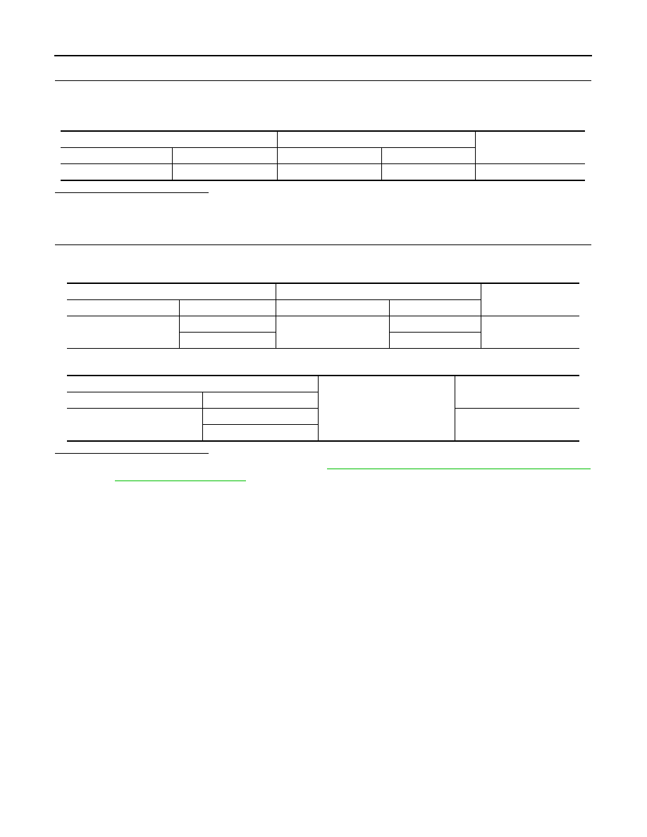
CHECK ENCODER SIGNAL CIRCUIT
1.
Check continuity between automatic back door control unit harness connector and automatic back door
unit harness connector.
2.
Check continuity between automatic back door control unit harness connector and ground.
Is the inspection result normal?
YES
>> Replace automatic back door unit. Refer to
DLK-354, "POWER BACK DOOR DRIVE ASSEMBLY
.
NO
>> Repair or replace harness.
Automatic back door control unit
Automatic back door unit
Continuity
Connector
Terminal
Connector
Terminal
B8
23
B76
6
Existed
Automatic back door control unit
Automatic back door unit
Continuity
Connector
Terminal
Connector
Terminal
B8
24
B76
5
Existed
25
1
Automatic back door control unit
Ground
Continuity
Connector
Terminal
B8
24
Not existed
25
CLUTCH
DLK-159
< DTC/CIRCUIT DIAGNOSIS >
[WITH INTELLIGENT KEY SYSTEM]
C
D
E
F
G
H
I
J
L
M
A
B
DLK
N
O
P
CLUTCH
Description
INFOID:0000000005517657
The clutch operates by the power supplied from the automatic back door control unit. It performs the duty con-
trol of the power supply to control the operation speed of the back door.
Diagnosis Procedure
INFOID:0000000005517658
1.
CHECK CLUTCH OUTPUT SIGNAL CIRCUIT
1.
Turn ignition switch OFF.
2.
Disconnect automatic back door control unit connector and automatic back door unit connector.
3.
Check continuity between automatic back door control unit harness connector and automatic back door
unit harness connector.
4.
Check continuity between automatic back door control unit harness connector and ground.
Is the inspection result normal?
YES
>> GO TO 2.
NO
>> Repair or replace harness.
2.
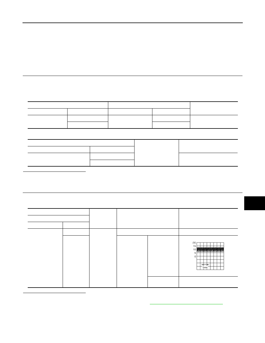
CHECK CLUTCH
1.
Connect automatic back door control unit connector and automatic back door unit connector.
2.
Check voltage between automatic back door control unit harness connector and ground.
Is the inspection result normal?
YES
>> Clutch is OK.
NO
>> Replace automatic back door control unit. Refer to
DLK-370, "Removal and Installation"
.
Automatic back door control unit
Automatic back door unit
Continuity
Connector
Terminal
Connector
Terminal
B7
32
B76
9
Existed
33
3
Automatic back door control unit
Ground
Continuity
Connector
Terminal
B7
32
Not existed
33
(+)
(–)
Condition
Voltage (V)
(Approx.)
Automatic back door control unit
Connector
Terminal
B7
32
Ground
—
0
33
Automatic back
door
Active
Other than
above
0
JMKIA1866ZZ
Нет комментариевНе стесняйтесь поделиться с нами вашим ценным мнением.
Текст