Nissan Murano Z51. Instruction — part 663
EM-124
< UNIT DISASSEMBLY AND ASSEMBLY >
CYLINDER BLOCK
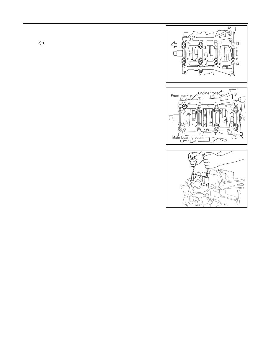
• Loosen main bearing cap bolts in the reverse order shown in
the figure in several different steps.
10. Remove main bearing beam.
11. Remove main bearing caps.
CAUTION:
Be careful not to drop main bearing, and to scratch the sur-
face.
• Using main bearing cap bolts, remove main bearing cap while
shaking it back-and-forth.
12. Remove crankshaft.
13. Remove main bearings and thrust bearings from cylinder block and main bearing caps.
CAUTION:
• Be careful not to drop main bearing, and to scratch the surface.
• Identify installation positions, and store them without mixing them up.
14. Remove oil jet.
ASSEMBLY
1.
Fully air-blow engine coolant and engine oil passages in cylinder block, cylinder bore and crankcase to
remove any foreign material.
CAUTION:
Use a goggles to protect your eye.
: Engine front
JPBIA0439ZZ
PBIC0881E
EMQ0195D
CYLINDER BLOCK
EM-125
< UNIT DISASSEMBLY AND ASSEMBLY >
C
D
E
F
G
H
I
J
K
L
M
A
EM
N
P
O
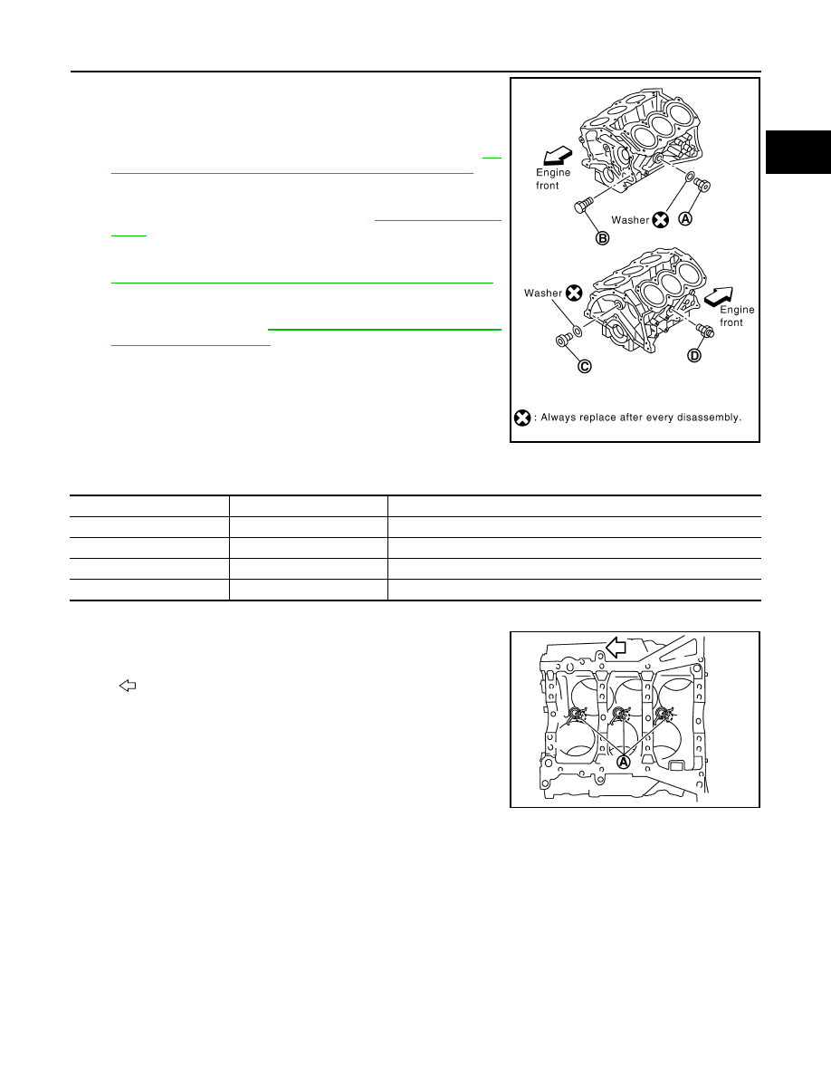
2.
Install each plug to cylinder block as shown in the figure.
• Apply sealant to the thread of water drain plug (A).
Use Anaerobic Liquid Gasket or equivalent. Refer to
18, "Recommended Chemical Products and Sealants"
.
NOTE:
For Canada, water drain plug (A) in the figure is not water
drain plug but block heater. Refer to
.
• Apply sealant to the thread of connector bolt (D).
Use Genuine RTV Silicone Sealant or equivalent. Refer to
GI-18, "Recommended Chemical Products and Sealants"
.
• Apply sealant to the thread of plug (C).
Use genuine high strength thread locking sealant or
equivalent. Refer to
• Replace washers with new one.
• Tighten each plug and connector bolt as specified below.
3.
Install oil jet.
• Insert oil jet dowel pin (A) into cylinder block dowel pin hole,
and tighten mounting bolts.
4.
Install main bearings and thrust bearings as follows:
CAUTION:
Be careful not to drop main bearing, and to scratch the surface.
a.
Remove dust, dirt, and engine oil on bearing mating surfaces of cylinder block and main bearing caps.
B
: Water drain plug
PBIC2487E
Part
Washer
Tightening torque
A
Yes
62.0 N·m (6.3 kg-m, 46 ft-lb)
B
No
9.8 N·m (1.0 kg-m, 87 in-lb)
C
Yes
62.0 N·m (6.3 kg-m, 46 ft-lb)
D
No
39.2 N·m (4.0 kg-m, 29 ft-lb)
: Engine front
JPBIA0198ZZ
EM-126
< UNIT DISASSEMBLY AND ASSEMBLY >
CYLINDER BLOCK
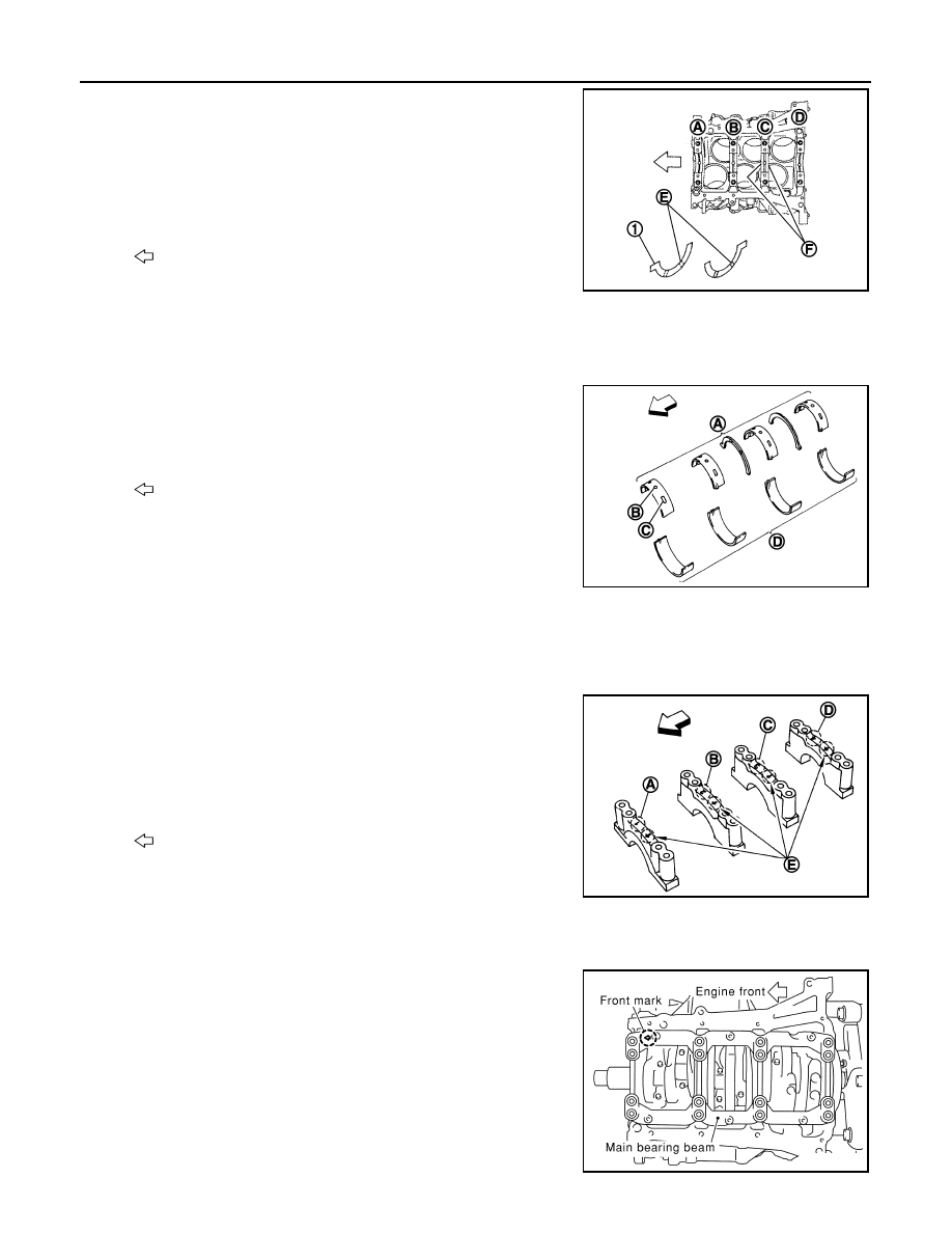
b.
Install thrust bearings (1) to the both sides of the No. 3 journal
housing on cylinder block and main bearing cap.
• Install thrust bearings with the oil groove (E) facing crankshaft
arm (outside).
• Install thrust bearing with a projection on one end on cylinder block, and thrust bearing with a projection
at center on main bearing cap. Align each projection with mating notch.
c.
Install main bearings paying attention to the direction.
• Main bearing with oil hole (B) and groove (C) goes on cylinder
block. The one without them goes on main bearing cap.
• Before installing main bearings, apply engine oil to the bearing
surface (inside). Do not apply engine oil to the back surface,
but thoroughly clean it.
• When installing, align main bearing stopper protrusion to cut-
out of cylinder block and main bearing caps.
• Ensure the oil holes on cylinder block and those on the corresponding bearing are aligned.
5.
Install crankshaft to cylinder block.
• While turning crankshaft by hand, check that it turns smoothly.
6.
Install main bearing caps.
• Main bearing caps are identified by identification mark cast on
them. For installation, face front mark (E) to front side.
NOTE:
Main bearing cap cannot be replaced as a single part, because it
is machined together with cylinder block.
7.
Install main bearing beam.
• Install main bearing beam with front mark facing downward (oil pan side).
• Install main bearing beam with front mark facing front of the
engine.
A
: No. 1
B
: No. 2
C
: No. 3
D
: No. 4
F
: Thrust bearing installation position
: Engine front
JPBIA0199ZZ
A
: Cylinder block side
D
: Main bearing cap side
: Engine front
JPBIA0200ZZ
A
: No. 1
B
: No. 2
C
: No. 3
D
: No. 4
: Engine front
JPBIA0440ZZ
PBIC0881E
CYLINDER BLOCK
EM-127
< UNIT DISASSEMBLY AND ASSEMBLY >
C
D
E
F
G
H
I
J
K
L
M
A
EM
N
P
O
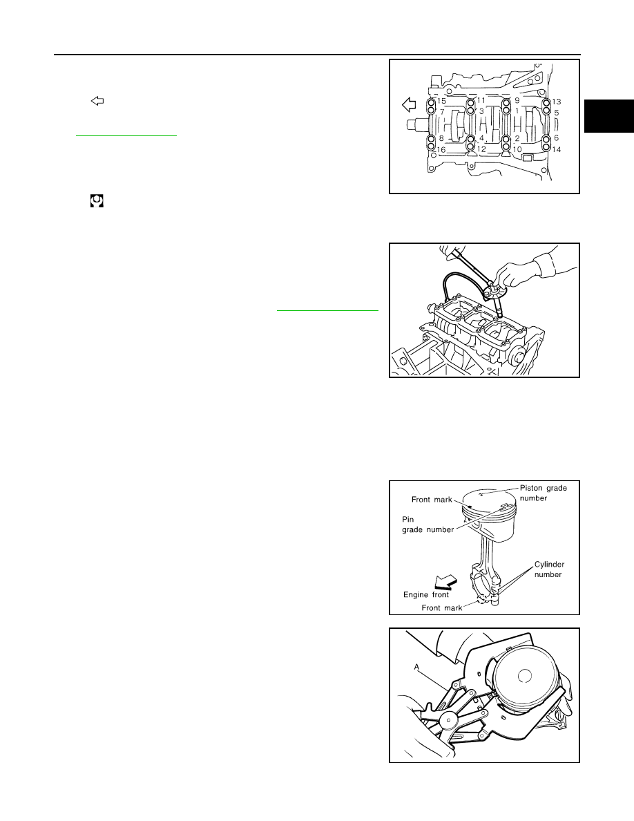
8.
Install main bearing cap bolts in numerical order as shown in the
figure as follows:
a.
Inspect the outer diameter of main bearing cap bolt. Refer to
.
b.
Apply new engine oil to threads and seat surfaces of main bear-
ing cap bolts.
c.
Tighten main bearing cap bolts in several different steps.
d.
Turn all main bearing cap bolts 90 degrees clockwise (angle tightening).
CAUTION:
Use the angle wrench [SST: KV10112100 (BT8653-A)] to
check tightening angle. Never make judgment by visual
inspection.
• After installing main bearing cap bolts, check that crankshaft
can be rotated smoothly by hand.
• Check the crankshaft end play. Refer to
9.
Install piston to connecting rod as follows:
a.
Using snap ring pliers, install new snap ring to the groove of piston rear side.
• Insert it fully into groove to install.
b.
Install piston to connecting rod.
• Using an industrial drier or similar tool, heat piston until piston pin can be pushed in by hand without
excess force [approximately 60 to 70
°
C (140 to 158
°
F)]. From the front to the rear, insert piston pin into
piston and connecting rod.
• Assemble so that the front mark on the piston crown and the
cylinder number on connecting rod are positioned as shown in
the figure.
c.
Install new snap ring to the groove of the piston front side.
• Insert it fully into groove to install.
• After installing, check that connecting rod moves smoothly.
10. Using a piston ring expander (commercial service tool) (A),
install piston rings.
CAUTION:
• When installing piston rings, be careful not to damage
piston.
• Be careful not to damage piston rings by expending them
excessively.
: Engine front
: 35.3 N·m (3.6 kg-m, 26 ft-lb)
JPBIA0439ZZ
PBIC0921E
SEM838F
JPBIA0194ZZ
Нет комментариевНе стесняйтесь поделиться с нами вашим ценным мнением.
Текст