Nissan Murano Z51. Instruction — part 525
EC-108
< SYSTEM DESCRIPTION >
[VQ35DE]
ON BOARD DIAGNOSTIC (OBD) SYSTEM
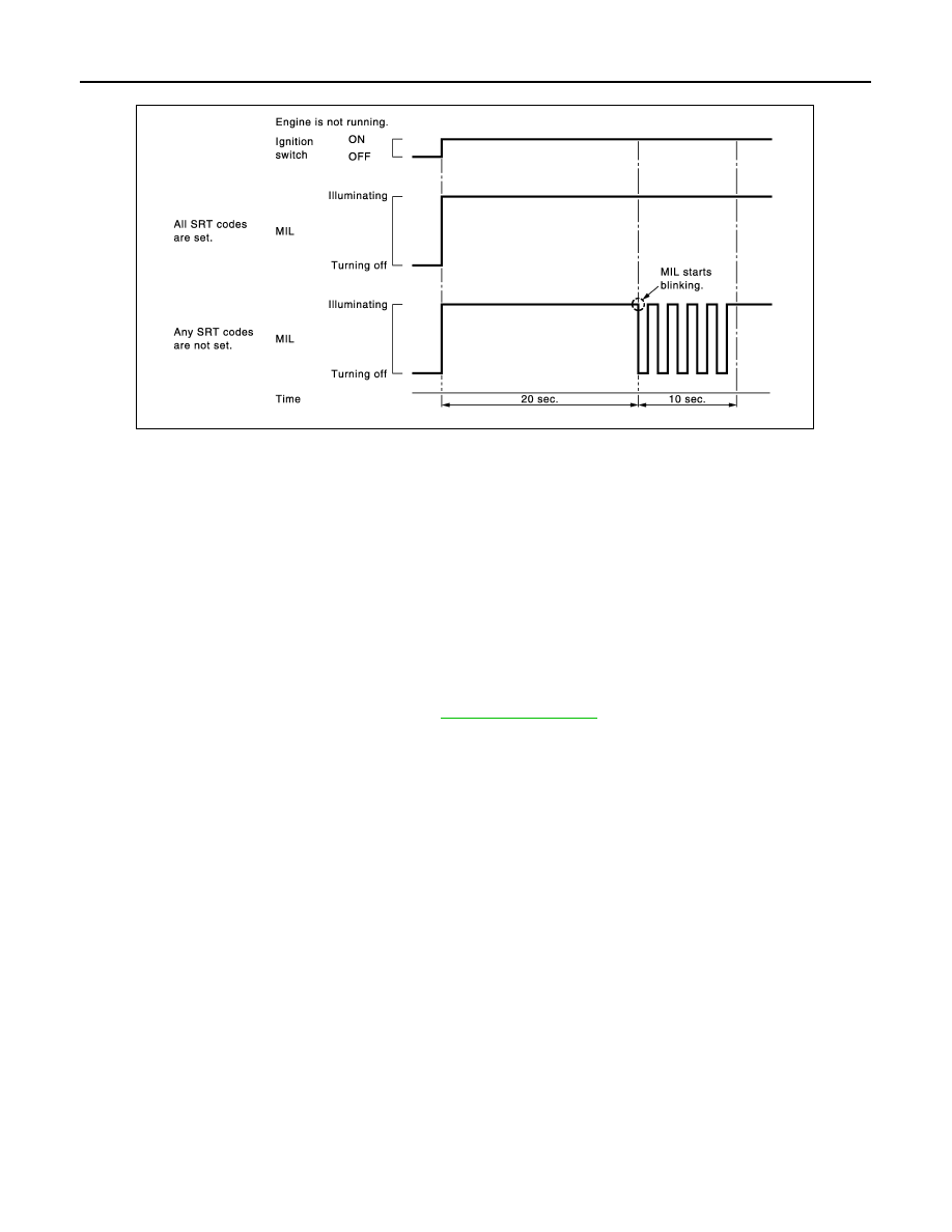
• When any SRT codes are not set, MIL will blink periodically for 10 seconds.
PERMANENT DIAGNOSTIC TROUBLE CODE (PERMANENT DTC)
Permanent DTC is defined in SAE J1979/ISO 15031-5 Service $0A.
ECM stores a DTC issuing a command of turning on MIL as a permanent DTC and keeps storing the DTC as
a permanent DTC until ECM judges that there is no presence of malfunction.
Permanent DTCs cannot be erased by using the Erase function of CONSULT-III or Generic Scan Tool (GST)
and by disconnecting the battery to shut off power to ECM. This prevents a vehicle from passing the state
emission inspection without repairing a malfunctioning part.
When not passing the state emission inspection due to more than one permanent DTC, permanent DTCs
should be erased, referring to this instruction.
NOTE:
• The important items in state emission inspection are that MIL is not ON, SRT test items are set, and perma-
nent DTCs are not included.
• Permanent DTCs do not apply for regions that permanent DTCs are not regulated by law.
Permanent DTC Item
For permanent DTC items, MIL turns on. Refer to
.
Permanent DTC Set Timing
The setting timing of permanent DTC is stored in ECM with the lighting of MIL when a DTC is confirmed.
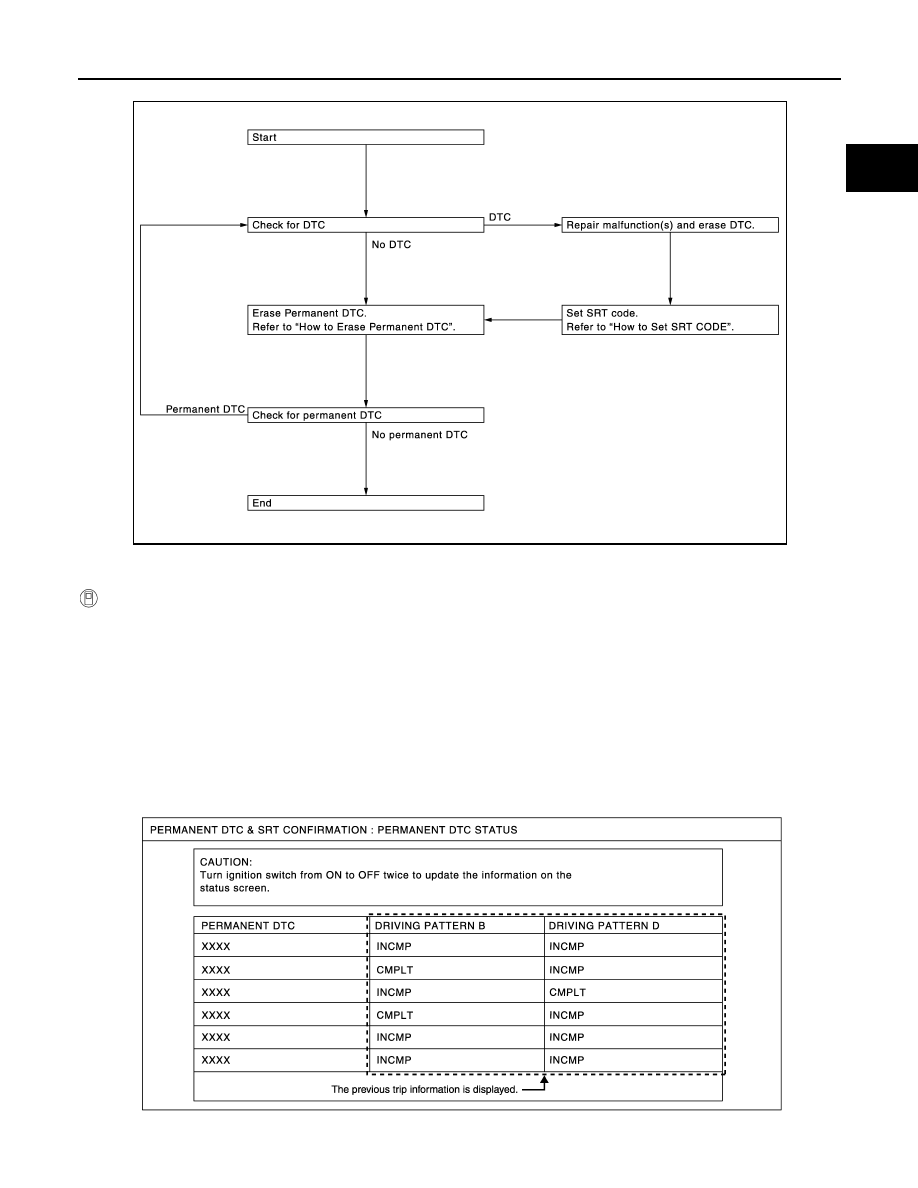
Permanent DTC Service Procedure
JMBIA1515GB
ON BOARD DIAGNOSTIC (OBD) SYSTEM
EC-109
< SYSTEM DESCRIPTION >
[VQ35DE]
C
D
E
F
G
H
I
J
K
L
M
A
EC
N
P
O
How to Display Permanent DTC Status
WITH CONSULT-III
1.
Turn ignition switch OFF and wait at least 10 seconds.
2.
Turn ignition switch ON.
3.
Turn ignition switch OFF and wait at least 10 seconds.
4.
Turn ignition switch ON.
5.
Select “PERMANENT DTC STATUS” in “DTC & SRT CONFIRMATION” mode with CONSULT-III.
NOTE:
Permanent DTCs stored in ECM memory are displayed on the CONSULT-III screen to show if a driving
pattern required for erasing permanent DTCs is complete (CMPLT) or incomplete (INCMP).
CAUTION:
Since the “PERMANENT DTC STATUS” screen displays the previous trip information, repeat the
following twice to update the information: “Ignition switch OFF”, “Wait for more than 10 seconds”
and “Ignition switch ON”.
JSBIA0066GB
JSBIA0062GB
EC-110
< SYSTEM DESCRIPTION >
[VQ35DE]
ON BOARD DIAGNOSTIC (OBD) SYSTEM
WITH GST
1.
Turn ignition switch OFF and wait at least 10 seconds.
2.
Turn ignition switch ON.
3.
Turn ignition switch OFF and wait at least 10 seconds.
4.
Turn ignition switch ON.
5.
Select Service $0A with GST (Generic Scan Tool).
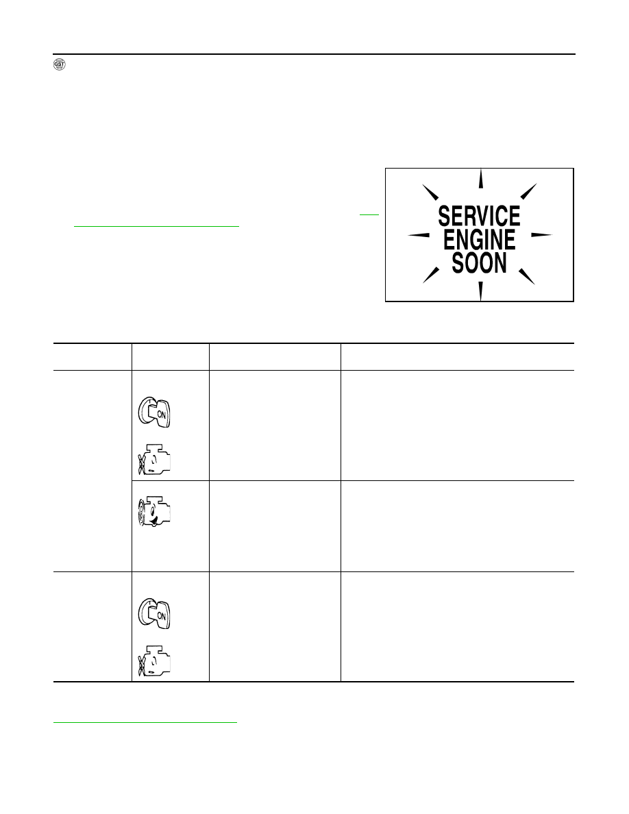
MALFUNCTION INDICATOR LAMP (MIL)
Description
The MIL is located on the instrument panel.
1.
The MIL will illuminate when the ignition switch is turned ON
without the engine running. This is a bulb check.
If the MIL does not illuminate, check MIL circuit. Refer to
450, "Component Function Check"
2.
When the engine is started, the MIL should turn off.
If the MIL remains on, the on board diagnostic system has
detected an engine system malfunction.
On Board Diagnostic System Function
The on board diagnostic system has the following three functions.
Diagnostic Test Mode I — Bulb Check
In this mode, the MIL on the instrument panel should stay ON. If it remains OFF, check MIL circuit. Refer to
EC-450, "Component Function Check"
Diagnostic Test Mode I — Malfunction Warning
SEF217U
Diagnostic Test
Mode
KEY and ENG.
Status
Function
Explanation of Function
Mode I
Ignition switch in
ON position
Engine stopped
BULB CHECK
This function checks the MIL bulb for damage (blown, open
circuit, etc.).
If the MIL does not illuminate, check MIL circuit.
Engine running
MALFUNCTION
WARNING
When a malfunction is detected twice in two consecutive
driving cycles (two trip detection logic), the MIL will illumi-
nate to inform the driver that a malfunction has been detect-
ed.
The following malfunctions will illuminate or blink the MIL in
the 1st trip.
• Misfire (Possible three way catalyst damage)
• One trip detection diagnoses
Mode II
Ignition switch in
ON position
Engine stopped
SELF-DIAGNOSTIC
RESULTS
This function allows DTCs and 1st trip DTCs to be read.
ON BOARD DIAGNOSTIC (OBD) SYSTEM
EC-111
< SYSTEM DESCRIPTION >
[VQ35DE]
C
D
E
F
G
H
I
J
K
L
M
A
EC
N
P
O
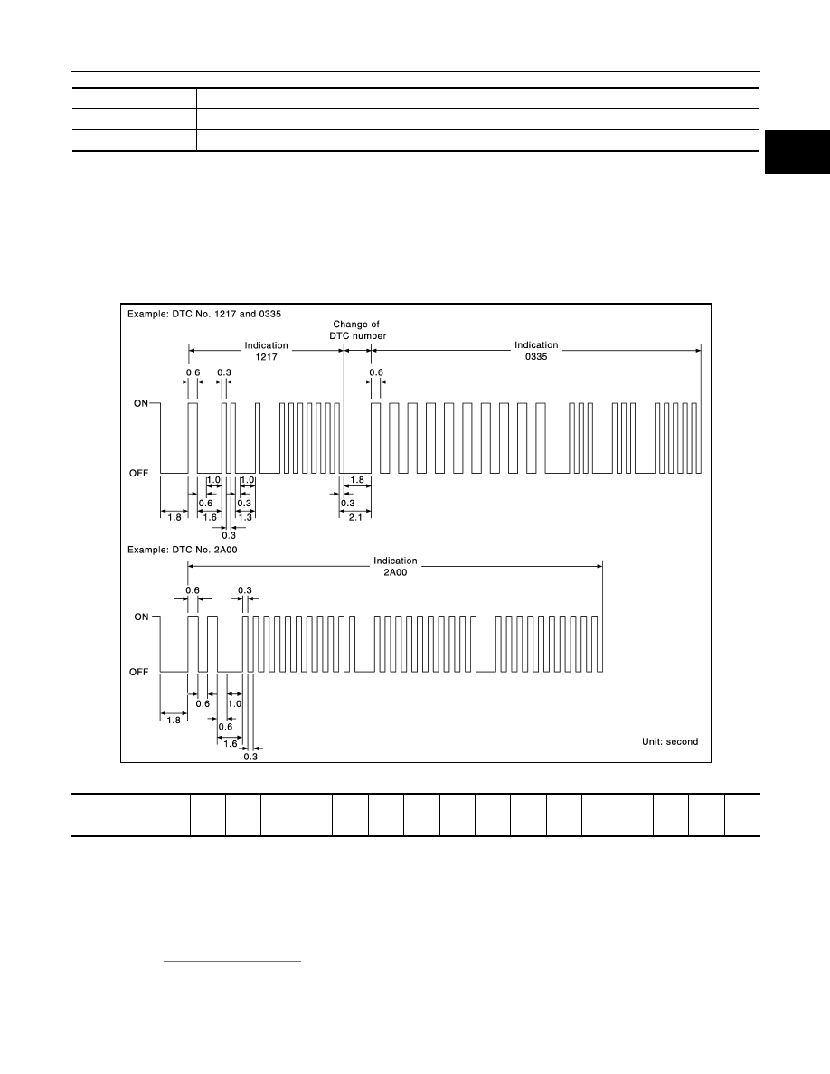
This DTC number is clarified in Diagnostic Test Mode II (SELF-DIAGNOSTIC RESULTS)
Diagnostic Test Mode II — Self-diagnostic Results
In this mode, the DTC and 1st trip DTC are indicated by the number of blinks of the MIL as shown below.
The DTC and 1st trip DTC are displayed at the same time. If the MIL does not illuminate in diagnostic test
mode I (Malfunction warning), all displayed items are 1st trip DTCs. If only one code is displayed when the MIL
illuminates in diagnostic test mode II (SELF-DIAGNOSTIC RESULTS), it is a DTC; if two or more codes are
displayed, they may be either DTCs or 1st trip DTCs. DTC No. is same as that of 1st trip DTC. These uniden-
tified codes can be identified by using the CONSULT-III or GST. A DTC will be used as an example for how to
read a code.
A particular trouble code can be identified by the number of four-digit numeral blinks as per the following.
The length of time the 1,000th-digit numeral flashes on and off is 1.2 seconds consisting of an ON (0.6-sec-
onds) - OFF (0.6-seconds) cycle.
The 100th-digit numeral and lower digit numerals consist of a 0.3-seconds ON and 0.3-seconds OFF cycle.
A change from one digit numeral to another occurs at an interval of 1.0-second OFF. In other words, the later
numeral appears on the display 1.3 seconds after the former numeral has disappeared.
A change from one trouble code to another occurs at an interval of 1.8-seconds OFF.
In this way, all the detected malfunctions are classified by their DTC numbers. The DTC 0000 refers to no mal-
function. (See
)
How to Switch Diagnostic Test Mode
NOTE:
• It is better to count the time accurately with a clock.
MIL
Condition
ON
When the malfunction is detected.
OFF
No malfunction.
JMBIA1140GB
Number
0
1
2
3
4
5
6
7
8
9
A
B
C
D
E
F
Blinks
10
1
2
3
4
5
6
7
8
9
11
12
13
14
15
16
Нет комментариевНе стесняйтесь поделиться с нами вашим ценным мнением.
Текст