Nissan Murano Z51. Instruction — part 512
EC-56
< SYSTEM DESCRIPTION >
[VQ35DE]
AUTOMATIC SPEED CONTROL DEVICE (ASCD)
1.
ECM
2.
IPDM E/R
3.
Fuel pump fuse
: Vehicle front
JMBIA1832GB
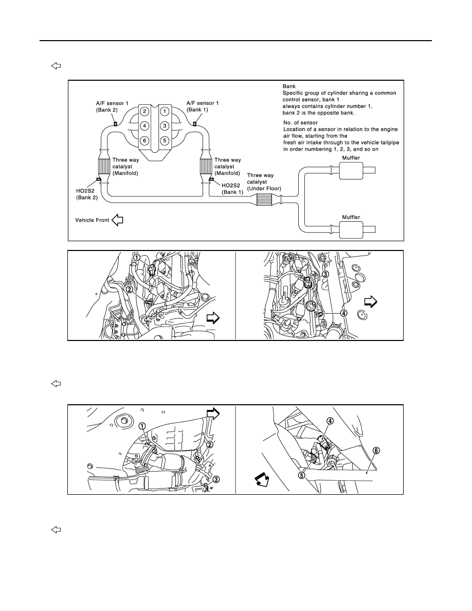
1.
A/F sensor 1 (bank 1) harness con-
nector
2.
A/F sensor 1 (bank 1)
3.
A/F sensor 1 (bank 2) harness con-
nector
4.
A/F sensor 1 (bank 2)
: Vehicle front
1.
HO2S2 (bank 1)
2.
HO2S2 (bank 2)
3.
HO2S2 (bank 2) harness connector
4.
HO2S2 (bank 1) harness connector
5.
Power steering pressure sensor
6.
Drive shaft (RH)
: Vehicle front
JMBIA1116ZZ
JMBIA1117ZZ
AUTOMATIC SPEED CONTROL DEVICE (ASCD)
EC-57
< SYSTEM DESCRIPTION >
[VQ35DE]
C
D
E
F
G
H
I
J
K
L
M
A
EC
N
P
O
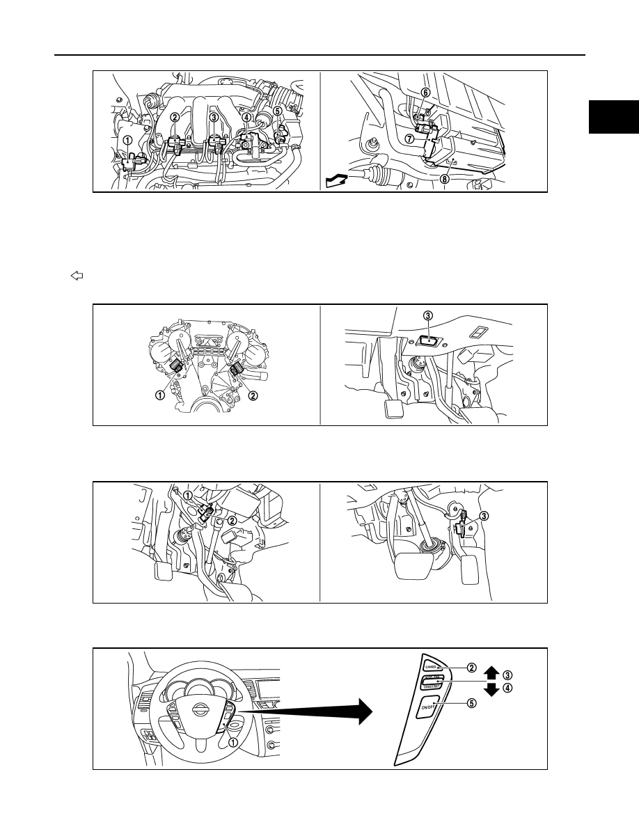
1.
Electronic controlled engine mount
control solenoid valve
2.
VIAS control solenoid valve 1
3.
VIAS control solenoid valve 2
4.
EVAP canister purge volume control
solenoid valve
5.
EVAP service port
6.
EVAP control system pressure sen-
sor
7.
EVAP canister vent control valve
8.
EVAP canister
: Vehicle front
1.
Intake valve timing control solenoid
valve (bank 1)
2.
Intake valve timing control solenoid
valve (bank 2)
3.
Data link connector
1.
Stop lamp switch
2.
ASCD brake switch
3.
Accelerator pedal position sensor
JMBIA1111ZZ
JMBIA1118ZZ
JMBIA1119ZZ
JMBIA1120ZZ
EC-58
< SYSTEM DESCRIPTION >
[VQ35DE]
AUTOMATIC SPEED CONTROL DEVICE (ASCD)
Component Description
INFOID:0000000005536504
1.
ASCD steering switch
2.
CANSEL switch
3.
RESUME/ACCELERATE switch
4.
SET/COAST switch
5.
MAIN switch
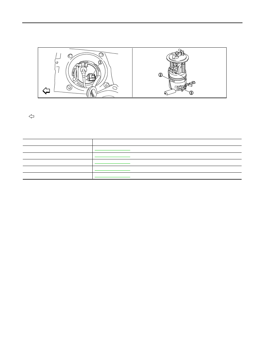
1.
Fuel level sensor unit and fuel pump
harness connector
2.
Fuel level sensor unit and fuel pump 3.
Fuel pressure regulator
: Vehicle front
JMBIA1121ZZ
Component
Reference
ASCD brake switch
ASCD indicator
ASCD steering switch
Electric throttle control actuator
Stop lamp switch
CAN COMMUNICATION
EC-59
< SYSTEM DESCRIPTION >
[VQ35DE]
C
D
E
F
G
H
I
J
K
L
M
A
EC
N
P
O
CAN COMMUNICATION
System Description
INFOID:0000000005536505
CAN (Controller Area Network) is a serial communication line for real time application. It is an on-vehicle mul-
tiplex communication line with high data communication speed and excellent error detection ability. Many elec-
tronic control units are equipped onto a vehicle, and each control unit shares information and links with other
control units during operation (not independent). In CAN communication, control units are connected with 2
communication lines (CAN H line, CAN L line) allowing a high rate of information transmission with less wiring.
Each control unit transmits/receives data but selectively reads required data only.
Refer to
LAN-27, "CAN Communication Signal Chart"
, about CAN communication for detail.
Нет комментариевНе стесняйтесь поделиться с нами вашим ценным мнением.
Текст