Nissan Murano Z51. Instruction — part 515
EC-68
< SYSTEM DESCRIPTION >
[VQ35DE]
ELECTRONIC CONTROLLED ENGINE MOUNT
ELECTRONIC CONTROLLED ENGINE MOUNT
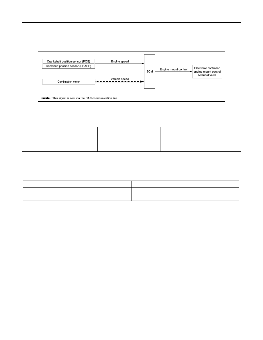
System Diagram
INFOID:0000000005536510
System Description
INFOID:0000000005536511
INPUT/OUTPUT SIGNAL CHART
*: This signal is sent to the ECM via the CAN communication line.
SYSTEM DESCRIPTION
The ECM controls the engine mount operation corresponding to the engine speed. The control system has a
2-step control [Soft/Hard]
ELECTRONIC CONTROLLED ENGINE MOUNT LINE DRAWING
JMBIA1827GB
Sensor
Input signal to ECM
ECM function
Actuator
Crankshaft position sensor (POS)
Camshaft position sensor (PHASE)
Engine speed
Engine mount
control
Electronic controlled en-
gine mount control solenoid
valve
Combination meter
Vehicle speed*
Vehicle condition
Engine mount control
Engine speed: Below 950 rpm
Soft
Engine speed: Above 950 rpm
Hard
ELECTRONIC CONTROLLED ENGINE MOUNT
EC-69
< SYSTEM DESCRIPTION >
[VQ35DE]
C
D
E
F
G
H
I
J
K
L
M
A
EC
N
P
O
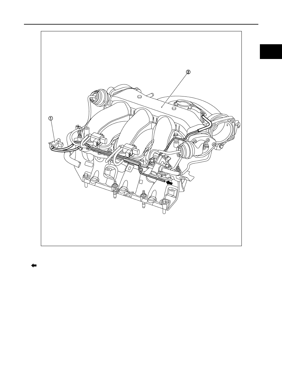
1.
Electronic controlled engine mount
control solenoid valve
2.
Intake manifold collector
: From next figure
JMBIA2161ZZ
EC-70
< SYSTEM DESCRIPTION >
[VQ35DE]
ELECTRONIC CONTROLLED ENGINE MOUNT
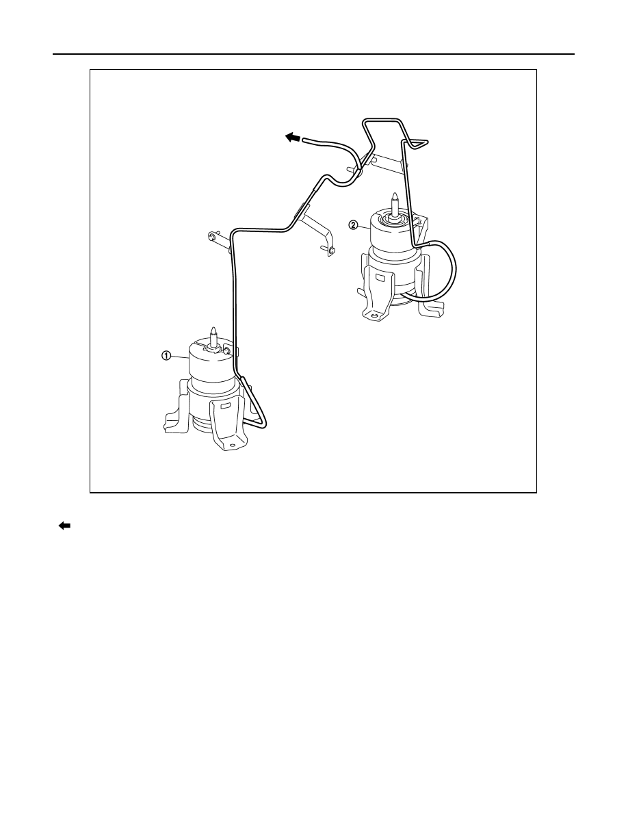
NOTE:
Do not use soapy water or any type of solvent while installing vacuum hose.
1.
Front electronic controlled engine mount 2.
Rear electronic controlled engine mount
: To previous figure
JMBIA2072ZZ
ELECTRONIC CONTROLLED ENGINE MOUNT
EC-71
< SYSTEM DESCRIPTION >
[VQ35DE]
C
D
E
F
G
H
I
J
K
L
M
A
EC
N
P
O
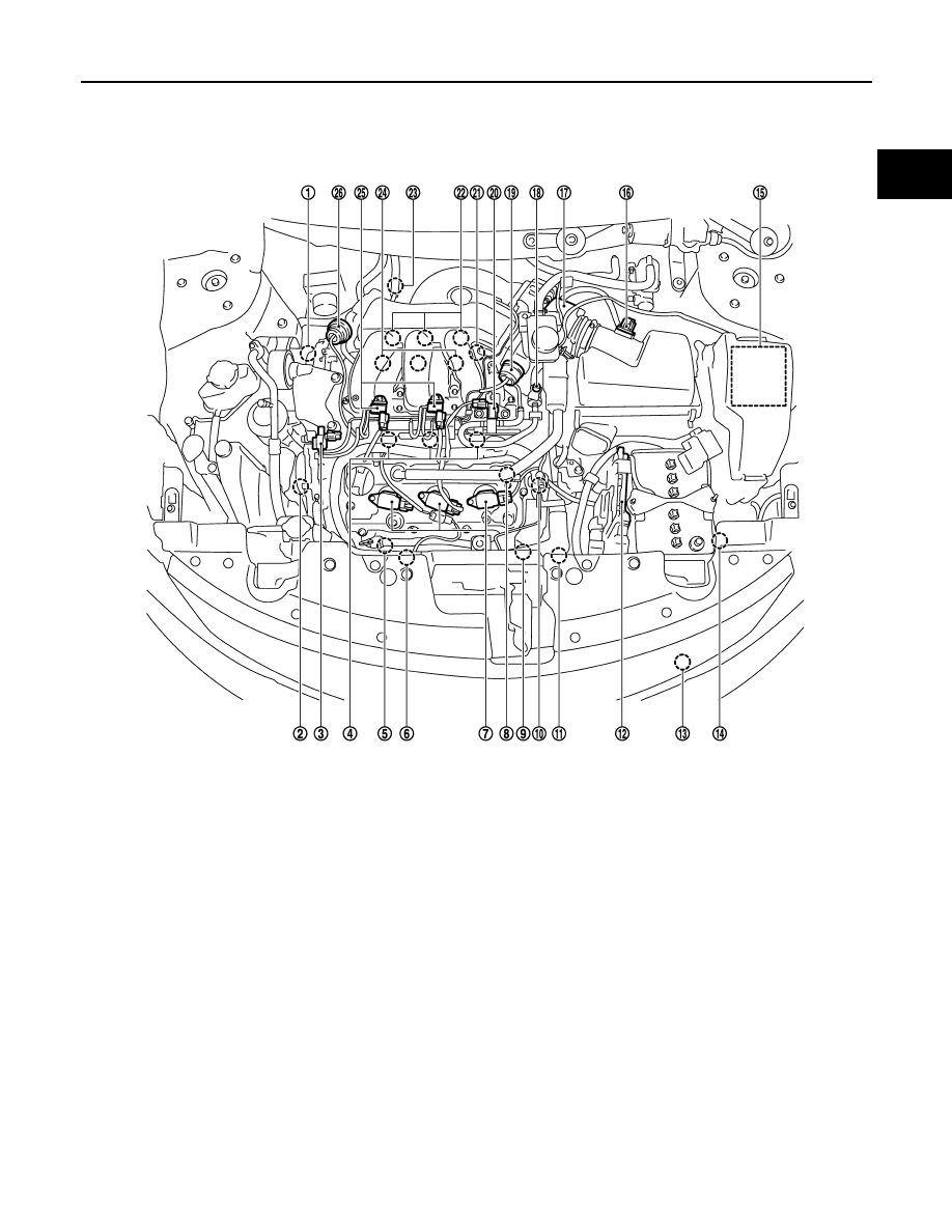
Component Parts Location
INFOID:0000000005536512
1.
Intake valve timing control solenoid
valve (bank 1)
2.
Intake valve timing control solenoid
valve (bank 2)
3.
Electronic controlled engine mount
control solenoid valve
4.
Fuel injector (bank 2)
5.
A/F sensor 1 (bank 2)
6.
Cooling fan motor-2
7.
Ignition coil (with power transistor)
and spark plug (bank 2)
8.
Camshaft position sensor (PHASE)
(bank 2)
9.
Crankshaft position sensor (POS)
10. Engine coolant temperature sensor
11.
Cooling fan motor-1
12. ECM
13. Refrigerant pressure sensor
14. Battery current sensor
15. IPDM E/R
16. Mass air flow sensor (with intake air
temperature sensor)
17. Electric throttle control actuator
18. EVAP service port
19. Power valve actuator 2
20. EVAP canister purge volume control
solenoid valve
21. Camshaft position sensor (PHASE)
(bank 1)
22. Ignition coil (with power transistor)
and spark plug (bank 1)
23. A/F sensor 1 (bank 1)
24. Fuel injector (bank 1)
25. VIAS control solenoid valve 1 and 2
26. Power valve actuator 1
JMBIA1108ZZ
Нет комментариевНе стесняйтесь поделиться с нами вашим ценным мнением.
Текст