Nissan Murano Z51. Instruction — part 1022
MIR-44
< ECU DIAGNOSIS INFORMATION >
[WITH ADP]
AUTOMATIC DRIVE POSITIONER CONTROL UNIT
AUTOMATIC DRIVE POSITIONER CONTROL UNIT
Reference Value
INFOID:0000000005712158
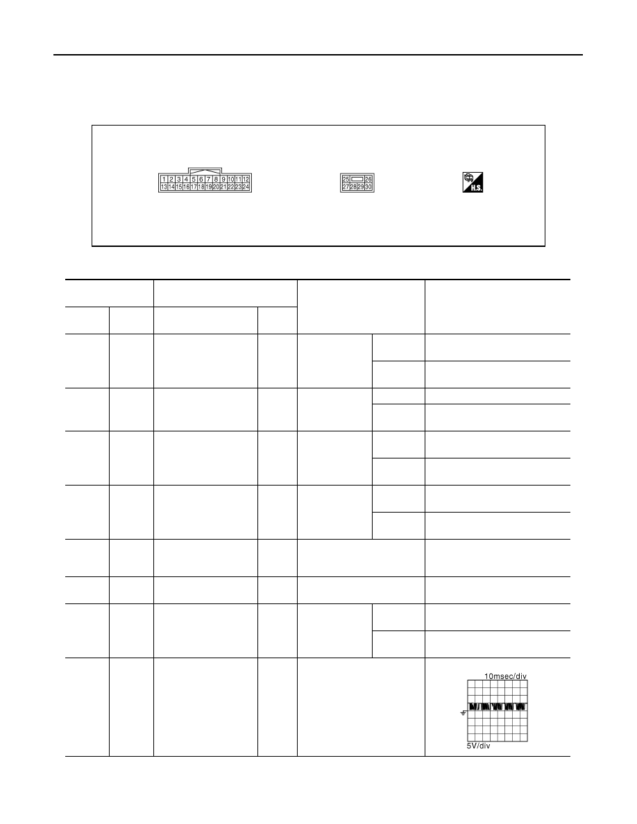
TERMINAL LAYOUT
PHYSICAL VALUES
JMJIA1389ZZ
Terminal No.
(wire color)
Description
Condition
Voltage (V)
(Approx.)
+
-
Signal name
Input/
Output
1
(Y)
Ground
Tilt switch up signal
Input
Tilt switch
Operate
(up)
0
Other than
above
5
2
(GR)
Ground
Changeover switch RH
signal
Input
Changeover
switch position
RH
0
Neutral or
LH
5
3
(SB)
Ground
Mirror switch up signal
Input
Mirror switch
Operated
(up)
0
Other than
above
5
4
(LG)
Ground
Mirror switch left signal
Input
Mirror switch
Operated
(left)
0
Other than
above
5
5
(R)
Ground
Door mirror sensor (pas-
senger side) up/down
signal
Input
Door mirror RH position
Change between 3.4 (close to
peak) 0.6 (close to valley)
6
(Y)
Ground
Door mirror sensor (driv-
er side) up/down signal
Input
Door mirror LH position
Change between 3.4 (close to
peak) 0.6 (close to valley)
7
(P)
Ground
Telescopic switch for-
ward signal
Input
Telescopic
switch
Operate
(forward)
0
Other than
above
5
8
(LG)
Ground
UART communication
(TX/RX)
Output
Ignition switch ON
JMJIA1391ZZ

AUTOMATIC DRIVE POSITIONER CONTROL UNIT
MIR-45
< ECU DIAGNOSIS INFORMATION >
[WITH ADP]
C
D
E
F
G
H
I
J
K
M
A
B
MIR
N
O
P
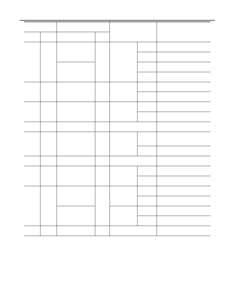
10
(O)
Ground
Door mirror motor (pas-
senger side) up output
signal
Output
Door mirror RH
Operate
(up)
Battery voltage
Other than
above
0
11
(G)
Ground
Door mirror motor (pas-
senger side) left output
signal
Output
Door mirror RH
Operate
(left)
Battery voltage
Other than
above
0
12
(R)
Ground
Door mirror motor (driv-
er side) down output sig-
nal
Output
Door mirror (LH)
Operate
(down)
Battery voltage
Other than
above
0
Door mirror motor (driv-
er side) right output sig-
nal
Operate
(right)
Battery voltage
Other than
above
0
13
(LG)
Ground
Tilt switch down signal
Input
Tilt switch
Operate
(down)
0
Other than
above
5
14
(O)
Ground
Changeover switch LH
signal
Input
Changeover
switch position
LH
0
Neutral or
RH
5
15
(L)
Ground
Mirror switch down sig-
nal
Input
Mirror switch
Operate
(down)
0
Other than
above
5
16
(V)
Ground
Mirror switch right signal
Input
Mirror switch
Operate
(right)
0
Other than
above
5
17
(W)
Ground
Door mirror sensor (pas-
senger side) left/right
signal
Input
Door mirror RH position
Change between 3.4 (close to left
edge) 0.6 (close to right edge)
18
(L)
Ground
Door mirror sensor (driv-
er side) left/right signal
Input
Door mirror LH position
Change between 0.6 (close to left
edge) 3.4 (close to right edge)
19
(G)
Ground
Telescopic switch back-
ward signal
Input
Telescopic
switch
Operate
(back-
ward)
0
Other than
above
5
20
(Y)
Ground
Ground
—
—
0
21
(W)
Ground
Door mirror motor sen-
sor power supply
Input
—
5
Terminal No.
(wire color)
Description
Condition
Voltage (V)
(Approx.)
+
-
Signal name
Input/
Output
MIR-46
< ECU DIAGNOSIS INFORMATION >
[WITH ADP]
AUTOMATIC DRIVE POSITIONER CONTROL UNIT
22
(V)
Ground
Door mirror motor (pas-
senger side) down out-
put signal
Output
Door mirror (RH)
Operate
(down)
Battery voltage
Other than
above
0
Door mirror motor (pas-
senger side) right output
signal
Operate
(right)
Battery voltage
Other than
above
0
23
(L)
Ground
Door mirror motor (driv-
er side)up output signal
Output
Door mirror (LH)
Operate
(up)
Battery voltage
Other than
above
0
24
(SB)
Ground
Door mirror motor (driv-
er side)left output signal
Output
Door mirror (LH)
Operate
(left)
Battery voltage
Other than
above
0
25
(W)
Ground
Power source
Input
—
Battery voltage
26
(L)
Ground
Telescopic motor back-
ward output signal
Output
Steering tele-
scopic
Operate
(back-
ward)
Battery voltage
Other than
above
0
27
(P)
Ground
Tilt&telescopic motor
power source
—
Battery voltage
28
(G)
Ground
Tilt motor down output
signal
Output
Steering tilt
Operate
(down)
Battery voltage
Other than
above
0
29
(LG)
Ground
Tilt motor up output sig-
nal
Output
Steering tilt
Operate
(up)
Battery voltage
Other than
above
0
Telescopic motor for-
ward output signal
Steering tele-
scopic
Operate
(forward)
Battery voltage
Other than
above
0
30
(B)
Ground
Ground
—
—
0
Terminal No.
(wire color)
Description
Condition
Voltage (V)
(Approx.)
+
-
Signal name
Input/
Output
AUTOMATIC DRIVE POSITIONER CONTROL UNIT
MIR-47
< ECU DIAGNOSIS INFORMATION >
[WITH ADP]
C
D
E
F
G
H
I
J
K
M
A
B
MIR
N
O
P
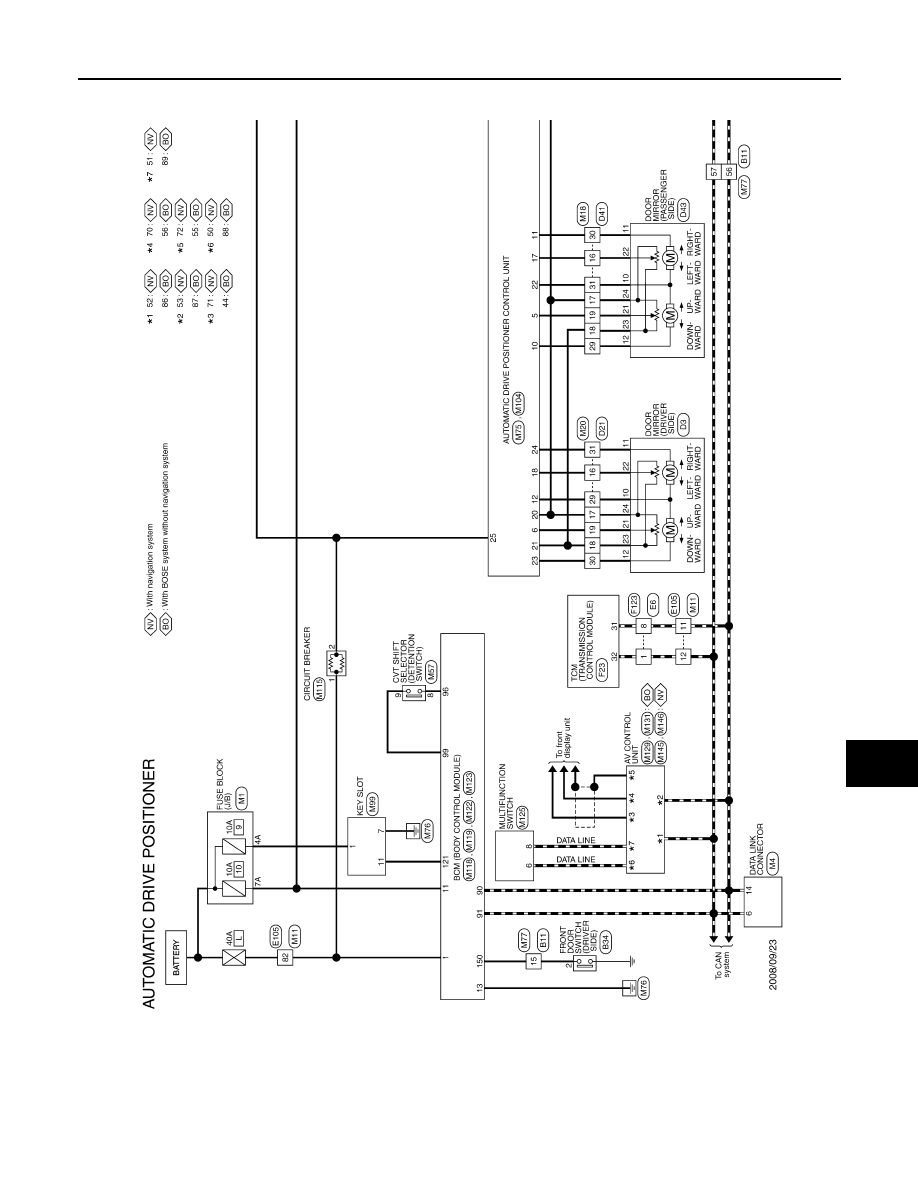
Wiring Diagram - AUTOMATIC DRIVE POSITIONER CONTROL SYSTEM -
INFOID:0000000005716145
JCJWM0709GB
Нет комментариевНе стесняйтесь поделиться с нами вашим ценным мнением.
Текст