Nissan Murano Z51. Instruction — part 1067

PCS-10
< SYSTEM DESCRIPTION >
[IPDM E/R]
DIAGNOSIS SYSTEM (IPDM E/R)
DIAGNOSIS SYSTEM (IPDM E/R)
Diagnosis Description
INFOID:0000000005516940
AUTO ACTIVE TEST
Description
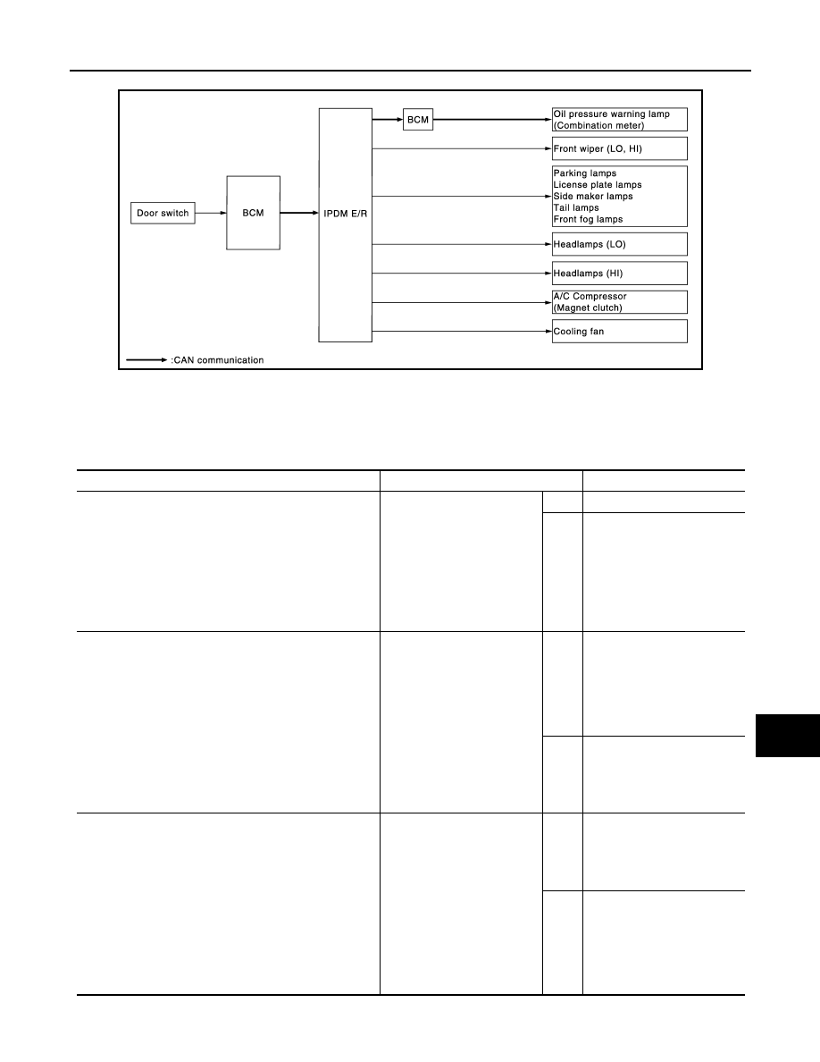
In auto active test mode, the IPDM E/R sends a drive signal to the following systems to check their operation.
• Oil pressure warning lamp
• Front wiper (LO, HI)
• Parking lamps
• License plate lamps
• Side maker lamps
• Tail lamps
• Front fog lamps
• Headlamps (LO, HI)
• A/C compressor (magnet clutch)
• Cooling fan
Operation Procedure
1.
Close the hood and lift the wiper arms from the windshield. (Prevent windshield damage due to wiper
operation)
NOTE:
When auto active test is performed with hood opened, sprinkle water on windshield beforehand.
2.
Turn the ignition switch OFF.
3.
Turn the ignition switch ON, and within 20 seconds, press the front door switch (driver side) 10 times.
Then turn the ignition switch OFF.
CAUTION:
Close passenger door.
4.
Turn the ignition switch ON within 10 seconds. After that the horn sounds once and the auto active test
starts.
5.
The oil pressure warning lamp starts blinking when the auto active test starts.
6.
After a series of the following operations is repeated 3 times, auto active test is completed.
NOTE:
When auto active test mode has to be cancelled halfway through test, turn the ignition switch OFF.
CAUTION:
• If auto active test mode cannot be actuated, check door switch system. Refer to
AUTOMATIC BACK DOOR : Component Function Check"
• Do not start the engine.
Inspection in Auto Active Test Mode
When auto active test mode is actuated, the following 6 steps are repeated 3 times.
Operation
sequence
Inspection location
Operation
1
Oil pressure warning lamp
Blinks continuously during operation of auto active test
2
Front wiper
LO for 5 seconds
→
HI for 5 seconds
3
• Parking lamps
• License plate lamps
• Side maker lamps
• Tail lamps
• Front fog lamps
10 seconds
4
Headlamps
LO
⇔
HI 5 times
5
A/C compressor (magnet clutch)
ON
⇔
OFF 5 times
6
Cooling fan
LO for 5 seconds
→
MID for 3 seconds
→
HI for 2 seconds
PCS
DIAGNOSIS SYSTEM (IPDM E/R)
PCS-11
< SYSTEM DESCRIPTION >
[IPDM E/R]
C
D
E
F
G
H
I
J
K
L
B
A
O
P
N
Concept of auto active test
• IPDM E/R starts the auto active test with the door switch signals transmitted by BCM via CAN communica-
tion. Therefore, the CAN communication line between IPDM E/R and BCM is considered normal if the auto
active test starts successfully.
• The auto active test facilitates troubleshooting if any systems controlled by IPDM E/R cannot be operated.
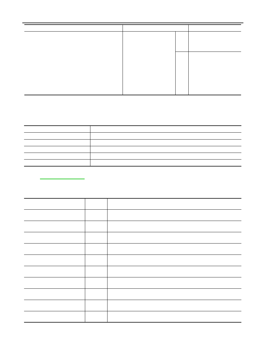
Diagnosis chart in auto active test mode
JPMIA0909GB
Symptom
Inspection contents
Possible cause
Any of the following components do not operate
• Parking lamps
• License plate lamps
• Side maker lamps
• Tail lamps
• Front fog lamps
• Headlamp (HI, LO)
• Front wiper (HI, LO)
Perform auto active test.
Does the applicable system
operate?
YES
BCM signal input circuit
NO
• Lamp or motor
• Lamp or motor ground cir-
cuit
• Harness or connector be-
tween IPDM E/R and appli-
cable system
• IPDM E/R
A/C compressor does not operate
Perform auto active test.
Does the magnet clutch oper-
ate?
YES
• A/C amp. signal input circuit
• CAN communication signal
between A/C amp. and
ECM
• CAN communication signal
between ECM and IPDM E/
R
NO
• Magnet clutch
• Harness or connector be-
tween IPDM E/R and mag-
net clutch
• IPDM E/R
Oil pressure warning lamp does not operate
Perform auto active test.
Does the oil pressure warning
lamp blink?
YES
• Harness or connector be-
tween IPDM E/R and oil
pressure switch
• Oil pressure switch
• IPDM E/R
NO
• CAN communication signal
between IPDM E/R and
BCM
• CAN communication signal
between BCM and combi-
nation meter
• Combination meter
PCS-12
< SYSTEM DESCRIPTION >
[IPDM E/R]
DIAGNOSIS SYSTEM (IPDM E/R)
CONSULT-III Function (IPDM E/R)
INFOID:0000000005516941
APPLICATION ITEM
CONSULT-III performs the following functions via CAN communication with IPDM E/R.
SELF DIAGNOSTIC RESULT
DATA MONITOR
Monitor item
Cooling fan does not operate
Perform auto active test.
Does the cooling fan operate?
YES
• ECM signal input circuit
• CAN communication signal
between ECM and IPDM E/
R
NO
• Harness or connector be-
tween IPDM E/R and cool-
ing fan motor
• Harness or connector be-
tween IPDM E/R and cool-
ing fan relay
• Cooling fan motor
• Cooling fan relay
• IPDM E/R
Symptom
Inspection contents
Possible cause
Diagnosis mode
Description
Ecu Identification
Allows confirmation of IPDM E/R part number.
Self Diagnostic Result
Displays the diagnosis results judged by IPDM E/R.
Data Monitor
Displays the real-time input/output data from IPDM E/R input/output data.
Active Test
IPDM E/R can provide a drive signal to electronic components to check their operations.
CAN Diag Support Monitor
The results of transmit/receive diagnosis of CAN communication can be read.
Monitor Item
[Unit]
MAIN SIG-
NALS
Description
MOTOR FAN REQ
[1/2/3/4]
×
Displays the value of the cooling fan speed request signal received from ECM via
CAN communication.
AC COMP REQ
[Off/On]
×
Displays the status of the A/C compressor request signal received from ECM via
CAN communication.
TAIL&CLR REQ
[Off/On]
×
Displays the status of the position light request signal received from BCM via CAN
communication.
HL LO REQ
[Off/On]
×
Displays the status of the low beam request signal received from BCM via CAN
communication.
HL HI REQ
[Off/On]
×
Displays the status of the high beam request signal received from BCM via CAN
communication.
FR FOG REQ
[Off/On]
×
Displays the status of the front fog light request signal received from BCM via
CAN communication.
FR WIP REQ
[Stop/1LOW/Low/Hi]
×
Displays the status of the front wiper request signal received from BCM via CAN
communication.
WIP AUTO STOP
[STOP P/ACT P]
×
Displays the status of the front wiper auto stop signal judged by IPDM E/R.
WIP PROT
[Off/BLOCK]
×
Displays the status of the front wiper fail-safe operation judged by IPDM E/R.
IGN RLY1 -REQ
[Off/On]
Displays the status of the ignition switch ON signal received from BCM via CAN
communication.
PCS
DIAGNOSIS SYSTEM (IPDM E/R)
PCS-13
< SYSTEM DESCRIPTION >
[IPDM E/R]
C
D
E
F
G
H
I
J
K
L
B
A
O
P
N
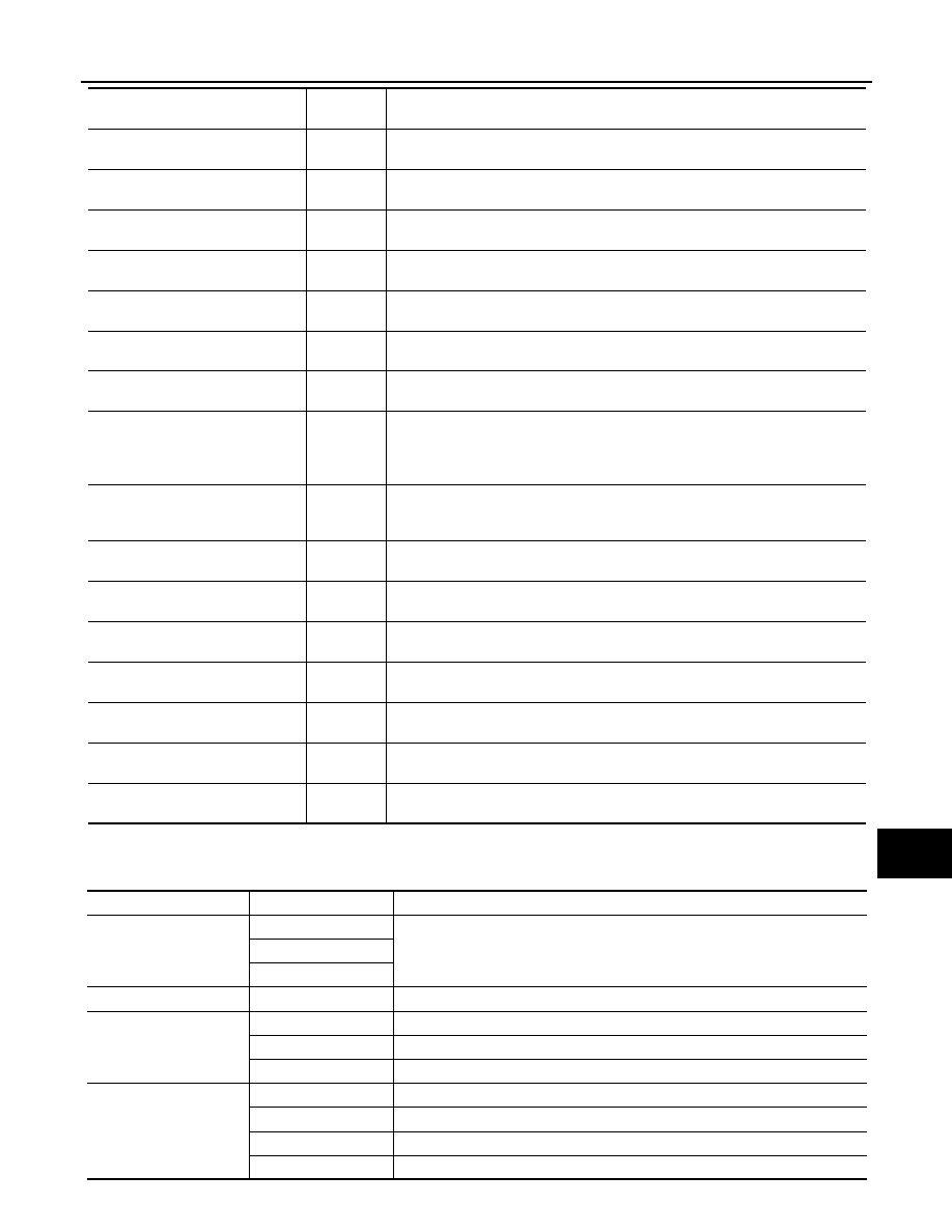
ACTIVE TEST
Test item
IGN RLY
[Off/On]
×
Displays the status of the ignition relay judged by IPDM E/R.
PUSH SW
[Off/On]
Displays the status of the push-button ignition switch judged by IPDM E/R.
INTER/NP SW
[Off/On]
Displays the status of the shift position judged by IPDM E/R.
ST RLY CONT
[Off/On]
Displays the status of the starter relay status signal received from BCM via CAN
communication.
IHBT RLY -REQ
[Off/On]
Displays the status of the starter control relay signal received from BCM via CAN
communication.
ST/INHI RLY
[Off/ ST ON/INHI ON/UNKWN]
Displays the status of the starter relay and starter control relay judged by IPDM
E/R.
DETENT SW
[Off/On]
Displays the status of the CVT shift selector (detention switch) judged by IPDM E/
R.
S/L RLY -REQ
[Off/On]
Displays the status of the steering lock relay signal received from BCM via CAN
communication.
NOTE:
For models without steering lock unit this item is not monitored.
S/L STATE
[LOCK/UNLOCK/UNKWN]
Displays the status of the steering lock judged by IPDM E/R.
NOTE:
For models without steering lock unit this item is not monitored.
DTRL REQ
[Off/On]
NOTE:
The item is indicated, but not monitored.
OIL P SW
[Open/Close]
Displays the status of the oil pressure switch judged by IPDM E/R.
HOOD SW
[Off/On]
NOTE:
The item is indicated, but not monitored.
HL WASHER REQ
[Off/On]
NOTE:
The item is indicated, but not monitored.
THFT HRN REQ
[Off/On]
Displays the status of the theft warning horn request signal received from BCM
via CAN communication.
HORN CHIRP
[Off/On]
Displays the status of the horn reminder signal received from BCM via CAN com-
munication.
CRNRNG LMP REQ
[Off/On]
NOTE:
The item is indicated, but not monitored.
Monitor Item
[Unit]
MAIN SIG-
NALS
Description
Test item
Operation
Description
CORNERING LAMP
Off
NOTE:
The item is indicated, but cannot be tested.
LH
RH
HORN
On
Operates horn relay for 20 ms.
FRONT WIPER
Off
OFF
Lo
Operates the front wiper relay.
Hi
Operates the front wiper relay and front wiper high relay.
MOTOR FAN
1
OFF
2
Operates the cooling fan relay-1.
3
Operates the cooling fan relay-2.
4
Operates the cooling fan relay-2 and cooling fan relay-3.
Нет комментариевНе стесняйтесь поделиться с нами вашим ценным мнением.
Текст