Nissan Murano Z51. Instruction — part 1223

SE-80
< ECU DIAGNOSIS INFORMATION >
REAR SEATBACK POWER RETURN CONTROL UNIT
Possible location of malfunction
Diagnosis mode
Corrective action
Return complete limit switch “ON” mal-
function
The return completion position cannot be de-
tected
Detect the lock with the rear seatback
power return control unit, and then re-
verse the power return motor
Return complete limit switch “OFF” mal-
function
The automatic return cannot be performed
because the return completion position is
misrecognized
The instruction return operation can be per-
formed
Primary position limit switch “ON” mal-
function
The initial position of the sector gear cannot
be detected
Detect the lock with the rear seatback
power return control unit, and then stop
the power return motor
* If the above condition is repeated for 4
times, stop the subsequent automatic re-
turn operation. However, the instruction re-
turn operation can be performed
Primary position limit switch “OFF” mal-
function
The initial position of the sector gear is mis-
recognized
(The sector gear reverse operation cannot be
performed)
• Return the sector gear to the initial po-
sition if the primary position limit switch
is not turned to ON after starting the re-
turn (Lock detection)
• The instruction return operation can be
performed
Sensor malfunction (fixed to High or
Low)
The motor lock is misrecognized because the
pulse does not change
• If the pulse does not change complete-
ly after starting the motor operation, re-
turn the sector gear to the initial
position
• The instruction return operation can be
performed
AUTOMATIC DRIVE POSITIONER CONTROL UNIT
SE-81
< ECU DIAGNOSIS INFORMATION >
C
D
E
F
G
H
I
K
L
M
A
B
SE
N
O
P
AUTOMATIC DRIVE POSITIONER CONTROL UNIT
Reference Value
INFOID:0000000005518213
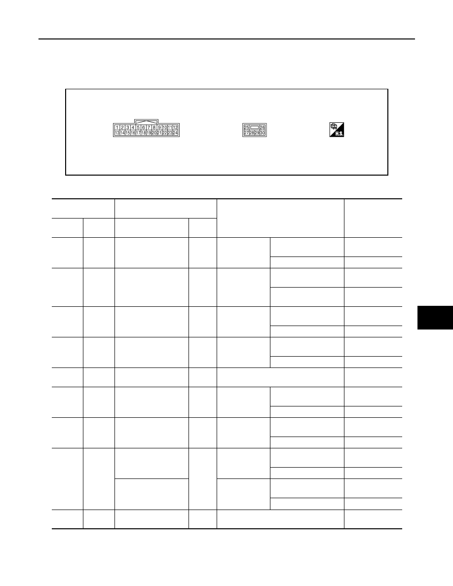
TERMINAL LAYOUT
PHYSICAL VALUES
JMJIA1389ZZ
Terminal No.
(wire color)
Description
Condition
Voltage (V)
(Approx.)
+
-
Signal name
Input/
Output
1
(Y)
Ground
Tilt switch upward signal
Input
Tilt switch
Operate
(upward)
0
Other than above
5
7
(P)
Ground
Telescopic switch for-
ward signal
Input
Telescopic
switch
Operate
(forward)
0
Other than above
5
13
(LG)
Ground
Tilt switch downward
signal
Input
Tilt switch
Operate
(downward)
0
Other than above
5
19
(G)
Ground
Telescopic switch back-
ward signal
Input
Telescopic
switch
Operate
(backward)
0
Other than above
5
25
(W)
Ground
Power source
Input
—
Battery voltage
26
(L)
Ground
Telescopic motor back-
ward output signal
Output
Steering tele-
scopic
Operate
(backward)
Battery voltage
Other than above
0
28
(G)
Ground
Tilt motor downward
output signal
Output
Steering tilt
Operate
(downward)
Battery voltage
Other than above
0
29
(LG)
Ground
Tilt motor upward output
signal
Output
Steering tilt
Operate
(upward)
Battery voltage
Other than above
0
Telescopic motor for-
ward output signal
Steering tele-
scopic
Operate
(forward)
Battery voltage
Other than above
0
30
(B)
Ground
Ground
—
—
0
SE-82
< ECU DIAGNOSIS INFORMATION >
AUTOMATIC DRIVE POSITIONER CONTROL UNIT
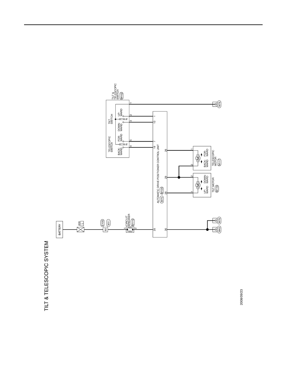
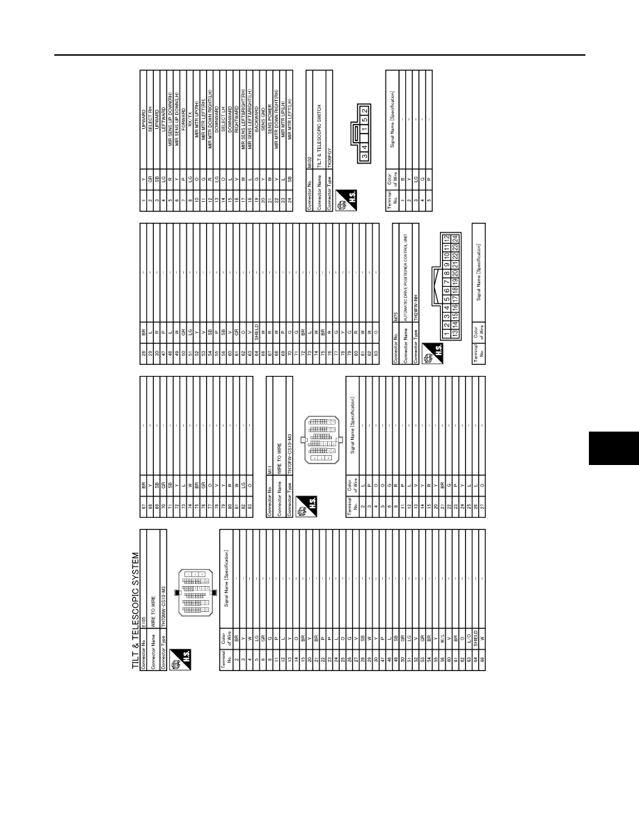
Wiring Diagram - TILT & TELESCOPIC SYSTEM -
INFOID:0000000005518214
JCJWM0689GB
AUTOMATIC DRIVE POSITIONER CONTROL UNIT
SE-83
< ECU DIAGNOSIS INFORMATION >
C
D
E
F
G
H
I
K
L
M
A
B
SE
N
O
P
JCJWM1005GB
Нет комментариевНе стесняйтесь поделиться с нами вашим ценным мнением.
Текст