Nissan Murano Z51. Instruction — part 1132
POWER WINDOW MOTOR
PWC-23
< DTC/CIRCUIT DIAGNOSIS >
C
D
E
F
G
H
I
J
L
M
A
B
PWC
N
O
P
4.
Check continuity between rear power window switch LH harness connector and ground.
Is the inspection result normal?
YES
>> Replace rear power window switch LH.Refer to
PWC-119, "Removal and Installation"
.
NO
>> Repair or replace harness.
3.
CHECK REAR POWER WINDOW MOTOR LH
Check rear power window motor LH.
Refer to
PWC-23, "REAR LH : Component Inspection"
Is the inspection result normal?
YES
>> GO TO 4.
NO
>> Replace rear power window motor LH. Refer to
GW-27, "Removal and Installation"
4.
CHECK INTERMITTENT INCIDENT
GI-39, "Intermittent Incident"
.
>> INSPECTION END
REAR LH : Component Inspection
INFOID:0000000005513338
COMPONENT INSPECTION
1.
CHECK REAR POWER WINDOW MOTOR LH
1.
Turn ignition switch OFF.
2.
Disconnect rear power window motor LH connector.
3.
Check motor operate by connecting the battery voltage directly to rear power window motor LH terminals.
Is the inspection result normal?
YES
>> INSPECTION END
NO
>> Replace rear power window motor LH. Refer to
GW-27, "Removal and Installation"
REAR RH
REAR RH : Description
INFOID:0000000005513339
Door glass moves UP/DOWN by receiving the signal from power window main switch or rear power window
switch RH.
REAR RH : Component Function Check
INFOID:0000000005513340
1.
CHECK REAR POWER WINDOW MOTOR RH OPERATION
Check rear power window motor RH operation with power window main switch or rear power window switch
RH.
Is the inspection result normal?
YES
>> Rear power window motor RH is OK.
NO
>> Refer to
PWC-24, "REAR RH : Diagnosis Procedure"
.
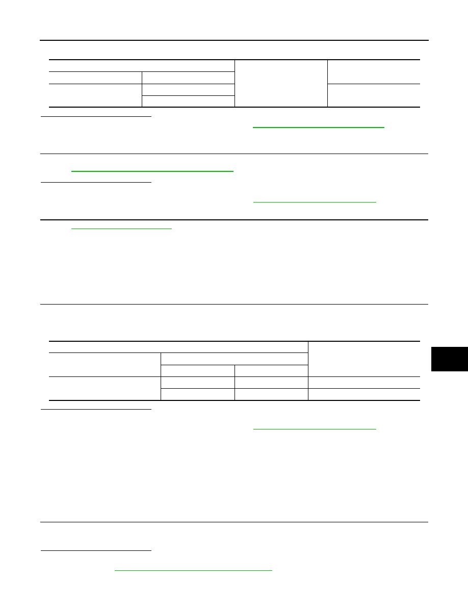
Rear power window switch LH
Ground
Continuity
Connector
Terminal
D83
4
Not existed
5
Rear power window motor LH
Motor condition
Connector
Terminal
(+)
(–)
D82
3
1
DOWN
1
3
UP
PWC-24
< DTC/CIRCUIT DIAGNOSIS >
POWER WINDOW MOTOR
REAR RH : Diagnosis Procedure
INFOID:0000000005513341
1.
CHECK REAR POWER WINDOW MOTOR RH INPUT SIGNAL
1.
Turn ignition switch OFF.
2.
Disconnect rear power window motor RH connector.
3.
Turn ignition switch ON.
4.
Check voltage between rear power window motor RH harness connector and ground.
Is the inspection result normal?
YES
>> GO TO 3.
NO
>> GO TO 2.
2.
CHECK REAR POWER WINDOW MOTOR RH CIRCUIT
1.
Turn ignition switch OFF.
2.
Disconnect rear power window switch RH connector.
3.
Check continuity between rear power window switch RH harness connector and rear power window motor
RH harness connector.
4.
Check continuity between rear power window switch RH harness connector and ground.
Is the inspection result normal?
YES
>> Replace rear power window switch RH.Refer to
PWC-119, "Removal and Installation"
.
NO
>> Repair or replace harness.
3.
CHECK REAR POWER WINDOW MOTOR RH
Check rear power window motor RH.
Refer to
PWC-25, "REAR RH : Component Inspection"
.
Is the inspection result normal?
YES
>> GO TO 4.
NO
>> Replace rear power window motor RH. Refer to
GW-27, "Removal and Installation"
.
4.
CHECK INTERMITTENT INCIDENT
GI-39, "Intermittent Incident"
>> INSPECTION END
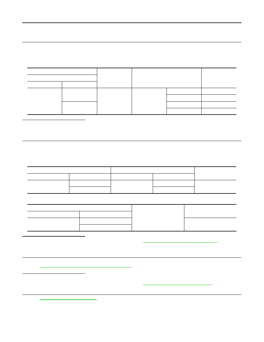
(+)
(–)
Condition
Voltage (V)
(Approx.)
Rear power window motor RH
Connector
Terminal
D102
1
Ground
Rear power win-
dow switch RH
UP
Battery voltage
DOWN
0
3
UP
0
DOWN
Battery voltage
Rear power window switch RH
Rear power window motor RH
Continuity
Connector
Terminal
Connector
Terminal
D103
4
D102
3
Existed
5
1
Rear power window switch RH
Ground
Continuity
Connector
Terminal
D103
4
Not existed
5
POWER WINDOW MOTOR
PWC-25
< DTC/CIRCUIT DIAGNOSIS >
C
D
E
F
G
H
I
J
L
M
A
B
PWC
N
O
P
REAR RH : Component Inspection
INFOID:0000000005513342
COMPONENT INSPECTION
1.
CHECK REAR POWER WINDOW MOTOR RH
1.
Turn ignition switch OFF.
2.
Disconnect rear power window motor RH connector.
3.
Check motor operation by connecting the battery voltage directly to rear power window motor RH termi-
nals.
Is the inspection result normal?
YES
>> INSPECTION END
NO
>> Replace rear power window motor RH. Refer to
GW-27, "Removal and Installation"
.
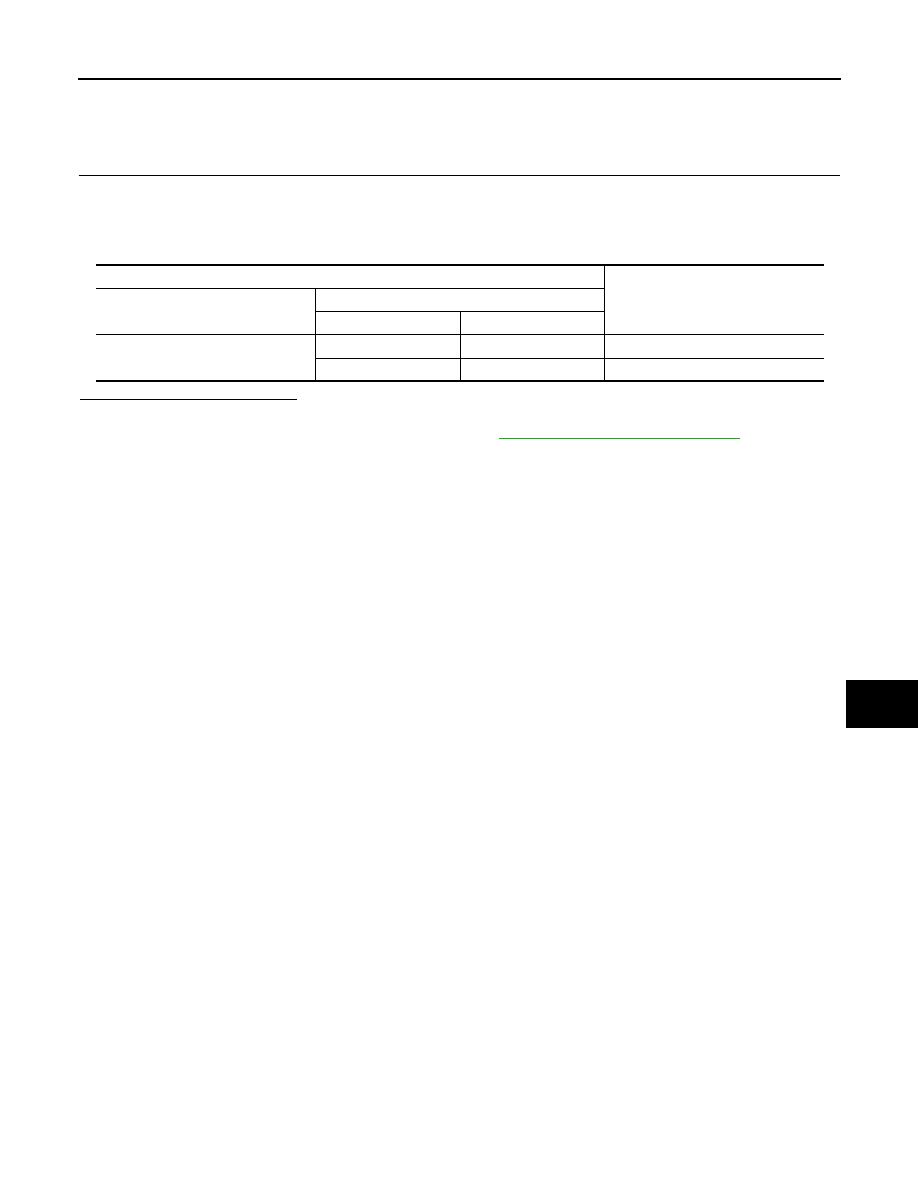
Rear power window motor RH
Motor condition
Connector
Terminal
(+)
(–)
D102
3
1
DOWN
1
3
UP
PWC-26
< DTC/CIRCUIT DIAGNOSIS >
ENCODER CIRCUIT
ENCODER CIRCUIT
DRIVER SIDE
DRIVER SIDE : Description
INFOID:0000000005513343
Detects condition of the front power window motor (driver side) operation and transmits to power window main
switch as the pulse signal.
DRIVER SIDE : Component Function Check
INFOID:0000000005513344
1.
CHECK ENCODER OPERATION
Check driver side door glass perform AUTO open/close operation normally by power window main switch.
Is the inspection result normal?
YES
>> Encoder is OK.
NO
>> Refer to
PWC-26, "DRIVER SIDE : Diagnosis Procedure"
DRIVER SIDE : Diagnosis Procedure
INFOID:0000000005513345
1.
CHECK ENCODER SIGNAL
1.
Turn ignition switch ON.
2.
Check signal between power window main switch harness connector and ground using oscilloscope.
Is the inspection result normal?
YES
>> Replace power window main switch. Refer to
PWC-119, "Removal and Installation"
.
NO
>> GO TO 2.
2.
CHECK ENCORDER SIGNAL CIRCUIT
1.
Turn ignition switch OFF.
2.
Disconnect power window main switch connector and front power window motor (driver side) connector.
3.
Check continuity between power window main switch harness connector and front power window motor
(driver side) harness connector.
4.
Check continuity between power window main switch harness connector and ground.
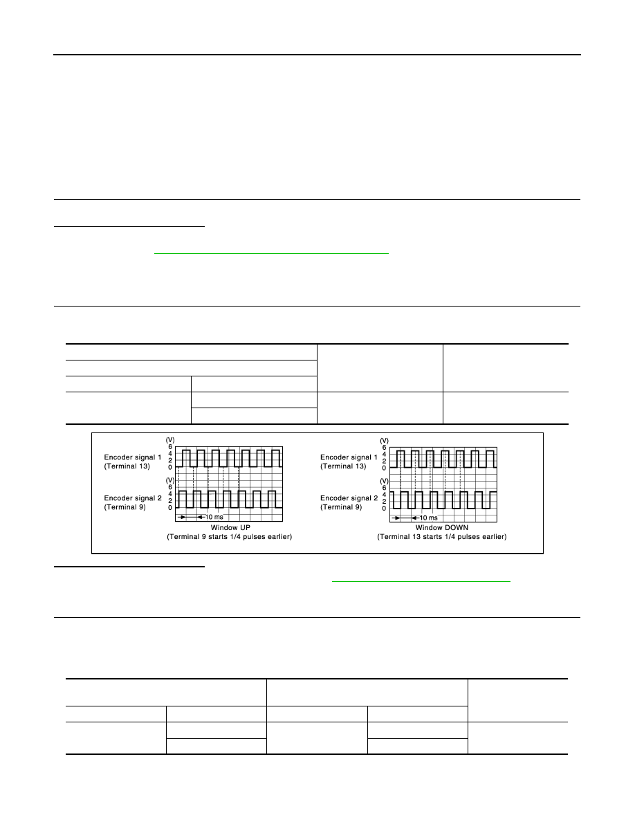
(+)
(–)
Signal
(Reference value)
Power window main switch
Connector
Terminal
D5
9
Ground
Refer to following signal
13
JMKIA2682GB
Power window main switch
Front power window motor
(driver side)
Continuity
Connector
Terminal
Connector
Terminal
D5
9
D7
3
Existed
13
5
Нет комментариевНе стесняйтесь поделиться с нами вашим ценным мнением.
Текст