Nissan Murano Z51. Instruction — part 296

DIAGNOSIS AND REPAIR WORK FLOW
BRC-7
< BASIC INSPECTION >
[VDC/TCS/ABS]
C
D
E
G
H
I
J
K
L
M
A
B
BRC
N
O
P
2.
PERFORM THE SELF-DIAGNOSIS
Perform self-diagnosis for “ABS” with CONSULT-III.
Is there any DTC displayed?
YES
>> GO TO 3.
NO
>> GO TO 4.
3.
PERFORM THE SYSTEM DIAGNOSIS
Perform the diagnosis applicable to the displayed DTC of “ABS” with CONSULT-III. Refer to
>> GO TO 7.
4.
CHECK THE SYMPTOM THAT IS NOT CONSIDERED A SYSTEM MALFUNCTION
Check that the symptom is a normal operation that is not considered a system malfunction. Refer to
Is the symptom a normal operation?
YES
>> GO TO 8.
NO
>> GO TO 5.
5.
CHECK THE WARNING LAMP AND INDICATOR LAMP FOR ILLUMINATION
Check that the warning lamp and indicator lamp illuminate.
• ABS warning lamp: Refer to
.
• Brake warning lamp: Refer to
• VDC OFF indicator lamp: Refer to
.
• SLIP indicator lamp: Refer to
.
Is ON/OFF timing normal?
YES
>> GO TO 6.
NO
>> GO TO 2.
6.
PERFORM THE DIAGNOSIS BY SYMPTOM
Perform the diagnosis applicable to the symptom for “ABS” with CONSULT-III.
>> GO TO 7.
7.
REPAIR OR REPLACE THE MALFUNCTIONING PARTS
Repair or replace the specified malfunctioning parts.
>> GO TO 8.
8.
MEMORY CLEAR
Perform self-diagnosis memory clear for “ABS” with CONSULT-III.
>> GO TO 9.
9.
FINAL CHECK
Perform the self-diagnosis again, and check that the malfunction is repaired completely.
Is no other DTC present and the repair completed?
YES
>> INSPECTION END
NO
>> GO TO 3.
BRC-8
< BASIC INSPECTION >
[VDC/TCS/ABS]
DIAGNOSIS AND REPAIR WORK FLOW
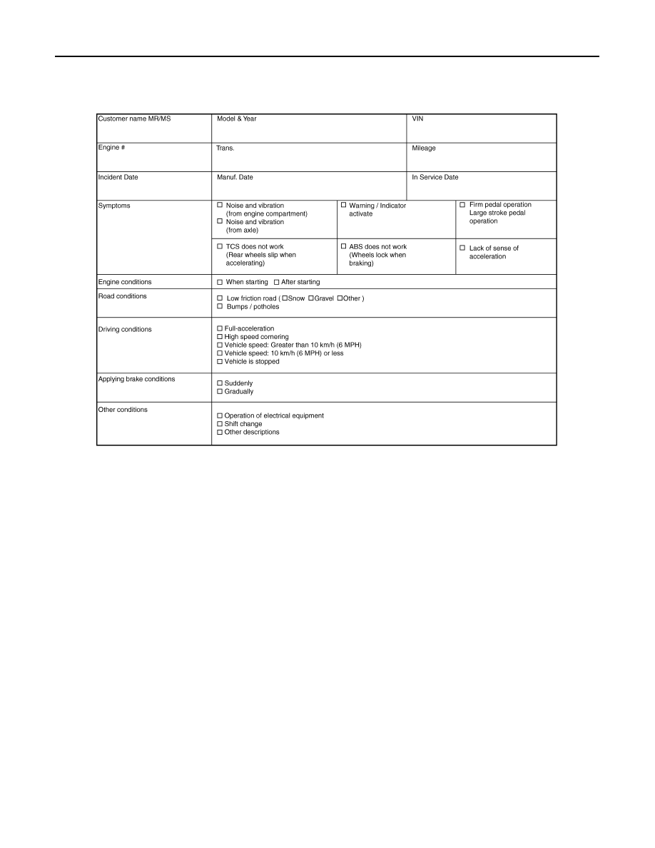
Diagnostic Work Sheet
INFOID:0000000005517249
SFIA3265E

INSPECTION AND ADJUSTMENT
BRC-9
< BASIC INSPECTION >
[VDC/TCS/ABS]
C
D
E
G
H
I
J
K
L
M
A
B
BRC
N
O
P
INSPECTION AND ADJUSTMENT
ADDITIONAL SERVICE WHEN REPLACING CONTROL UNIT
ADDITIONAL SERVICE WHEN REPLACING CONTROL UNIT : Description
INFOID:0000000005532111
Perform the steering angle sensor adjustment and decel G sensor calibration after replacing the ABS actuator
and electric unit (control unit).
ADDITIONAL SERVICE WHEN REPLACING CONTROL UNIT : Special Repair Re-
quirement
INFOID:0000000005532112
1.
PERFORM ADJUSTMENT OF STEERING ANGLE SENSOR AND CALIBRATION OF DECEL G SENSOR
Perform steering angle sensor adjustment and decel G sensor calibration.
• Adjustment of steering angle sensor: Refer to
BRC-9, "ADJUSTMENT OF STEERING ANGLE SENSOR
NEUTRAL POSITION : Description"
• Calibration of decel G sensor: Refer to
BRC-10, "CALIBRATION OF DECEL G SENSOR : Description"
.
>> INSPECTION END
ADJUSTMENT OF STEERING ANGLE SENSOR NEUTRAL POSITION
ADJUSTMENT OF STEERING ANGLE SENSOR NEUTRAL POSITION : Description
INFOID:0000000005517250
When doing work that applies to the list below, make sure to adjust neutral position of steering angle sensor
before running vehicle.
×
: Required –: Not required
ADJUSTMENT OF STEERING ANGLE SENSOR NEUTRAL POSITION : Special Re-
pair Requirement
INFOID:0000000005517251
ADJUSTMENT OF STEERING ANGLE SENSOR NEUTRAL POSITION
CAUTION:
To adjust neutral position of steering angle sensor, make sure to use CONSULT-III
(Adjustment cannot be done without CONSULT-III)
1.
ALIGN THE VEHICLE STATUS
Stop the vehicle with front wheels in straight-ahead position.
>> GO TO 2.
2.
PERFORM THE NEUTRAL POSITION ADJUSTMENT FOR THE STEERING ANGLE SENSOR
Situation
Adjustment of steering angle sensor neutral position
Removing/Installing ABS actuator and electric unit (control unit)
—
Replacing ABS actuator and electric unit (control unit)
×
Removing/Installing steering angle sensor
×
Replacing steering angle sensor
×
Removing/Installing steering components
×
Replacing steering components
×
Removing/Installing suspension components
×
Replacing suspension components
×
Change tires to new ones
—
Tire rotation
—
Adjusting wheel alignment
×

BRC-10
< BASIC INSPECTION >
[VDC/TCS/ABS]
INSPECTION AND ADJUSTMENT
1.
Select “ABS”, "WORK SUPPORT" and “ST ANGLE SENSOR ADJUSTMENT” in order with CONSULT-III.
2.
Select “START”.
CAUTION:
Never touch steering wheel while adjusting steering angle sensor.
3.
After approximately 10 seconds, select “END”.
NOTE:
After approximately 60 seconds, it ends automatically.
4.
Turn the ignition switch OFF, then turn it ON again.
CAUTION:
Be sure to perform above operation.
>> GO TO 3.
3.
CHECK DATA MONITOR
1.
Run the vehicle with front wheels in straight-ahead position, then stop.
2.
Select “ABS”, “DATA MONITOR” and “STR ANGLE SIG” in order with CONSULT-III, and check steering
angle sensor signal.
Is the steering angle within the specified range?
YES
>> GO TO 4.
NO
>> Perform the neutral position adjustment for the steering angle sensor again, GO TO 1.
4.
ERASE THE SELF-DIAGNOSIS MEMORY
Erase the self-diagnosis memories for “ABS” with CONSULT-III. Refer to
BRC-28, "CONSULT-III Function"
Are the memories erased?
YES
>> INSPECTION END
NO
>> Check the items indicated by the self-diagnosis.
CALIBRATION OF DECEL G SENSOR
CALIBRATION OF DECEL G SENSOR : Description
INFOID:0000000005517252
When doing work that applies to the list below, make sure to calibration of decel G sensor before running vehi-
cle.
×
: Required –: Not required
CALIBRATION OF DECEL G SENSOR : Special Repair Requirement
INFOID:0000000005517253
CALIBRATION OF DECEL G SENSOR
CAUTION:
• To calibrate decel G sensor, make sure to use CONSULT-III.
(Calibration cannot be done without CONSULT-III.)
• Perform the G sensor calibration only with the vehicle parked on level surface.
1.
ALIGN THE VEHICLE STATUS
STR ANGLE SIG
: 0
±
3.5
°
Situation
Calibration of decel G sensor
Removing/Installing ABS actuator and electric unit (control unit)
×
Replacing ABS actuator and electric unit (control unit)
×
Removing/Installing steering components
—
Removing/Installing suspension components
—
Change tires to new ones
—
Tire rotation
—
Adjusting wheel alignment
—
Removing/Installing yaw rate/side/decel G sensor
×
Replacing yaw rate/side/decel G sensor
×
Нет комментариевНе стесняйтесь поделиться с нами вашим ценным мнением.
Текст