Nissan Murano Z51. Instruction — part 1168
RF-12
< DTC/CIRCUIT DIAGNOSIS >
POWER SUPPLY AND GROUND CIRCUIT
Is the inspection result normal?
YES
>> GO TO 3.
NO
>> GO TO 2.
2.
CHECK SUNROOF MOTOR CIRCUIT
1.
Turn ignition switch OFF.
2.
Disconnect BCM connector.
3.
Check continuity between BCM harness connector and sunroof motor assembly harness connector.
4.
Check continuity between BCM harness connector and ground.
Is the inspection result normal?
YES
>> Refer to
BCS-95, "Removal and Installation"
.
NO
>> Repair or replace harness.
3.
CHECK GROUND CIRCUIT
1.
Turn ignition switch OFF.
2.
Check continuity between sunroof motor assembly harness connector and ground.
Is the inspection result normal?
YES
>> GO TO 4.
NO
>> Repair or replace harness.
4.
CHECK INTERMITTENT INCIDENT
GI-39, "Intermittent Incident"
>> INSPECTION END
SUNSHADE MOTOR ASSEMBLY
SUNSHADE MOTOR ASSEMBLY : Diagnosis Procedure
INFOID:0000000005516832
1.
CHECK POWER SUPPLY
1.
Turn ignition switch OFF.
2.
Disconnect sunshade motor assembly connector.
3.
Turn ignition switch ON.
(+)
(–)
Voltage (V)
(Approx.)
Sunroof motor assembly
Connector
Terminal
R101
3
Ground
Battery voltage
6
BCM
Sunroof motor assembly
Continuity
Connector
Terminal
Connector
Terminal
M118
2
R101
6
Existed
3
3
BCM
Ground
Continuity
Connector
Terminal
M118
2
Not existed
3
Sunroof motor assembly
Ground
Continuity
Connector
Terminal
R101
1
Existed
2
POWER SUPPLY AND GROUND CIRCUIT
RF-13
< DTC/CIRCUIT DIAGNOSIS >
C
D
E
F
G
H
I
J
L
M
A
B
RF
N
O
P
4.
Check voltage between sunshade motor assembly harness connector and ground.
Is the inspection result normal?
YES
>> GO TO 3.
NO
>> GO TO 2.
2.
CHECK SUNSHADE MOTOR CIRCUIT
1.
Turn ignition switch OFF.
2.
Disconnect BCM connector.
3.
Check continuity between BCM harness connector and sunshade motor assembly harness connector.
4.
Check continuity between BCM harness connector and ground.
Is the inspection result normal?
YES
>> Replace BCM. Refer to
BCS-95, "Removal and Installation"
NO
>> Repair or replace harness.
3.
CHECK GROUND CIRCUIT
1.
Turn ignition switch OFF.
2.
Check continuity between sunshade motor assembly harness connector and ground.
Is the inspection result normal?
YES
>> GO TO 4.
NO
>> Repair or replace harness.
4.
CHECK INTERMITTENT INCIDENT
GI-39, "Intermittent Incident"
.
>> INSPECTION END
(+)
(–)
Voltage (V)
(Approx.)
Sunshade motor assembly
Connector
Terminal
R102
6
Ground
Battery voltage
BCM
Sunshade motor assembly
Continuity
Connector
Terminal
Connector
Terminal
M118
2
R102
6
Existed
BCM
Ground
Continuity
Connector
Terminal
M118
2
Not existed
Sunshade motor assembly
Ground
Continuity
Connector
Terminal
R102
1
Existed
RF-14
< DTC/CIRCUIT DIAGNOSIS >
COMMUNICATION SIGNAL CIRCUIT
COMMUNICATION SIGNAL CIRCUIT
Description
INFOID:0000000005516833
Detects door open/close condition.
Diagnosis Procedure
INFOID:0000000005516834
1.
CHECK DOOR SWITCH INPUT SIGNAL
1.
Turn ignition switch OFF.
2.
Disconnect sunshade motor assembly connector.
3.
Turn ignition switch ON.
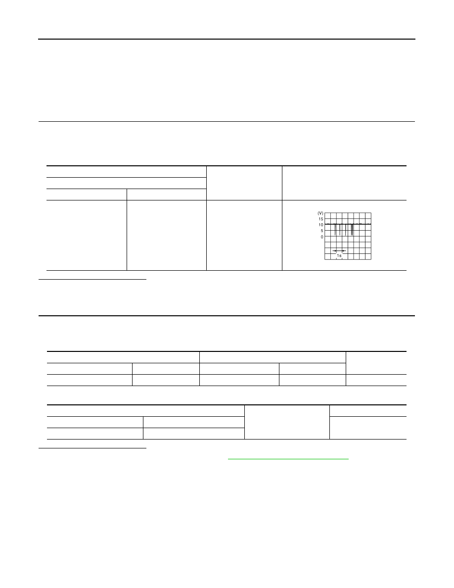
4.
Check signal between sunshade motor assembly harness connector and ground with oscilloscope.
Is the inspection result normal?
YES
>> INSPECTION END.
NO
>> GO TO 2.
2.
CHECK COMMUNICATION SIGNAL CIRCUIT
1.
Disconnect sunroof motor assembly connector.
2.
Check continuity between sunshade motor assembly harness connector and sunroof motor assembly har-
ness connector.
3.
Check continuity between sunshade motor assembly harness connector and ground.
Is the inspection result normal?
YES
>> Replace sunroof motor assembly. Refer to
RF-100, "Removal and Installation"
NO
>> Repair or replace harness.
(+)
(–)
Voltage (V)
(Approx.)
Sunshade motor assembly
Connector
Terminal
R102
7
Ground
JMKIA1869ZZ
Sunshade motor assembly
Sunroof motor assembly
Continuity
Connector
Terminal
Connector
Terminal
R102
7
R101
7
Existed
Sunshade motor assembly
Ground
Continuity
Connector
Terminal
Not existed
R102
7
SUNROOF SWITCH
RF-15
< DTC/CIRCUIT DIAGNOSIS >
C
D
E
F
G
H
I
J
L
M
A
B
RF
N
O
P
SUNROOF SWITCH
Description
INFOID:0000000005516835
Transmits switch operation signal to sunroof motor assembly.
Diagnosis Procedure
INFOID:0000000005516836
1.
CHECK SUNROOF SWITCH INPUT SIGNAL
1.
Turn ignition switch ON.
2.
Check voltage between sunroof motor assembly harness connector and ground.
Is the inspection result normal?
YES
>> Replace sunroof motor. Refer to
RF-98, "Removal and Installation"
.
NO
>> GO TO 2.
2.
CHECK SUNROOF SWITCH CIRCUIT
1.
Turn ignition switch OFF.
2.
Disconnect sunroof motor assembly connector and sunroof switch connector.
3.
Check continuity between sunroof motor assembly harness connector and sunroof switch harness con-
nector.
4.
Check continuity between sunroof motor assembly harness connector and ground.
Is the inspection result normal?
(+)
(–)
Condition
Voltage (V)
(Approx.)
Sunroof motor assembly
Connector
Terminals
R101
4
Ground
Sunroof switch is operated
PUSH
0
Other than above
Battery voltage
5
Sunroof switch is operated
OPEN (1st or 2nd)
0
Other than above
Battery voltage
9
Sunroof switch is operated
OPEN (2nd) or OPEN (2nd)
0
Other than above
Battery voltage
10
Sunroof switch is operated
CLOSE (1st or 2nd)
0
Other than above
Battery voltage
Sunroof motor assembly
Sunroof switch
Continuity
Connector
Terminal
Connector
Terminal
R101
4
R6
5
Existed
5
3
9
2
10
4
Sunroof motor assembly
Ground
Continuity
Connector
Terminal
R101
4
Not existed
5
9
10
Нет комментариевНе стесняйтесь поделиться с нами вашим ценным мнением.
Текст