Nissan Murano Z51. Instruction — part 834
HA-52
< REMOVAL AND INSTALLATION >
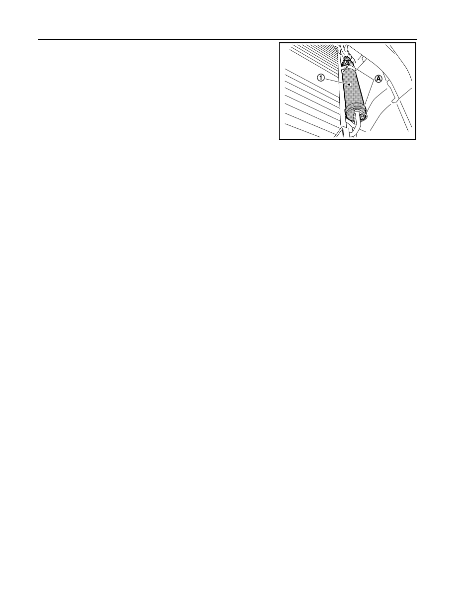
LIQUID TANK
5.
Remove the mounting bolts (A), and then remove the liquid tank
(1).
CAUTION:
Cap or wrap the joint of the A/C piping and liquid tank with
suitable material such as vinyl tape to avoid the entry of air.
INSTALLATION
Installation is basically the reverse order of removal.
CAUTION:
• Replace O-rings with new ones. Then apply compressor oil to them when installing.
• Check for leakages when recharging refrigerant.
JPIIA0545ZZ
REFRIGERANT PRESSURE SENSOR
HA-53
< REMOVAL AND INSTALLATION >
C
D
E
F
G
H
J
K
L
M
A
B
HA
N
O
P
REFRIGERANT PRESSURE SENSOR
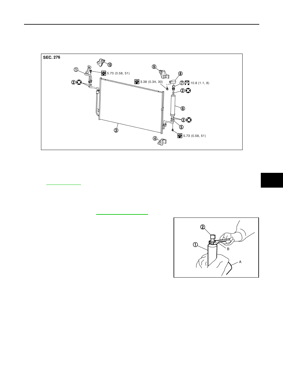
Exploded View
INFOID:0000000005514556
Removal and Installation
INFOID:0000000005514557
REMOVAL
1.
Remove liquid tank. Refer to
.
2.
Fix the liquid tank (1) with a vise (A). Remove the refrigerant
pressure sensor (2) with a wrench (B).
CAUTION:
• Be careful not to damage liquid tank.
• Seal the refrigerant pressure sensor on liquid tank with
caps, vinyl tape, or a similar item to prevent them from
being exposed to the atmosphere.
INSTALLATION
Installation is basically the reverse order of removal.
CAUTION:
• Replace the O-rig with a new one. Apply a coat of compressor oil to the O-ring prior to installation.
• Check for leakages when recharging refrigerant.
1.
Condenser pipe assembly
2.
O-ring
3.
Condenser assembly
4.
Condenser lower bracket LH
5.
Bracket
6.
Liquid tank
7.
Refrigerant pressure sensor
8.
Liquid tank bracket
9.
Condenser upper bracket LH
10. Condenser upper bracket RH
Refer to
JPIIA0460GB
JSIIA0075ZZ
HA-54
< REMOVAL AND INSTALLATION >
EVAPORATOR PIPE ASSEMBLY
EVAPORATOR PIPE ASSEMBLY
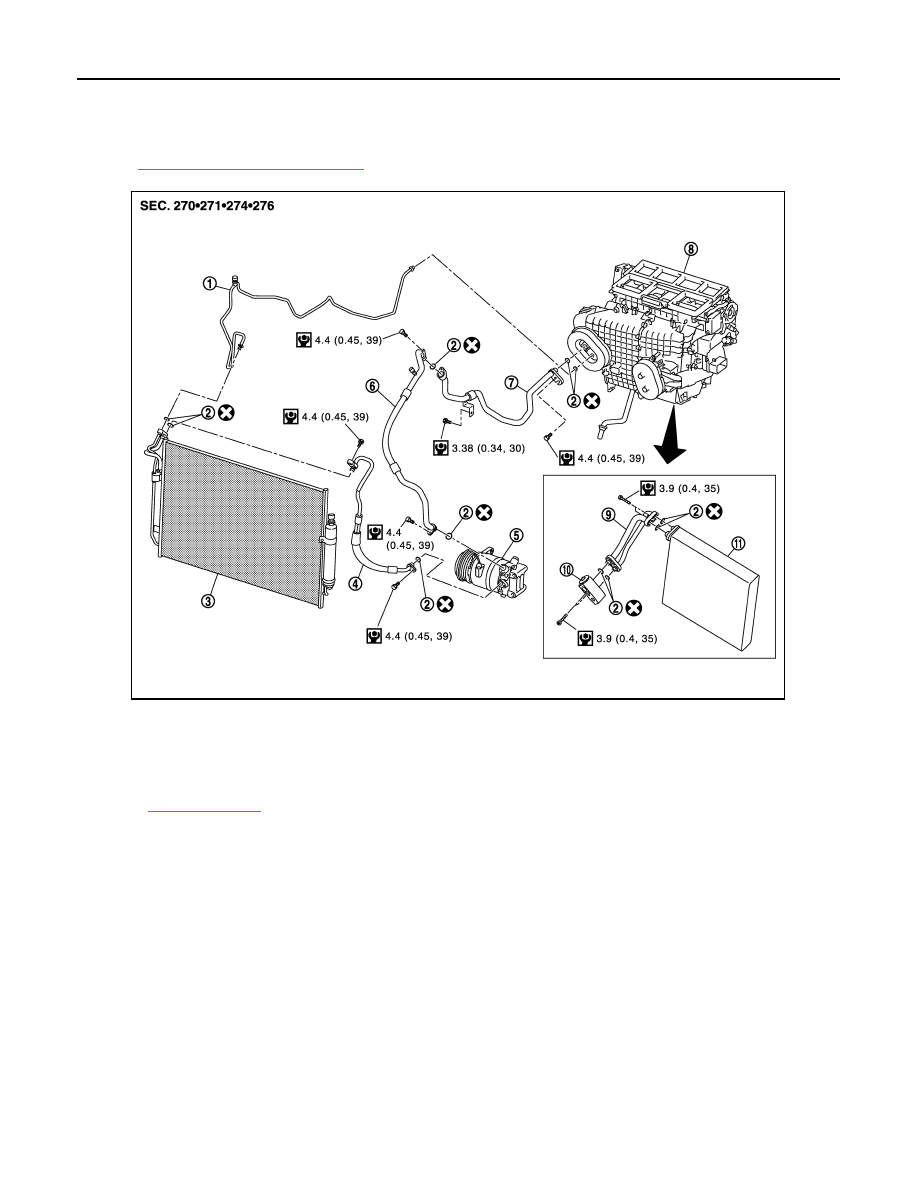
Exploded View
INFOID:0000000005514558
HA-15, "Refrigerant Connection"
.
Removal and Installation
INFOID:0000000005514559
REMOVAL
1.
Set the temperature (passenger side) at 18
°
C (60
°
F).
CAUTION:
The angle may be out, when installing the air mix door motor to the air mix door, unless the above
procedure is performed.
2.
Disconnect the battery cable from the negative terminal.
3.
Use refrigerant collecting equipment (for HFC-134a) to discharge the refrigerant.
1.
High-pressure pipe
2.
O-ring
3.
Condenser assembly
4.
High-pressure flexible hose
5.
Compressor
6.
Low-pressure flexible hose
7.
Low-pressure pipe
8.
Heater & cooling unit assembly
9.
Evaporator pipe assembly
10. Expansion valve
11.
Evaporator
Refer to
for symbols in the figure.
JPIIA1257GB
EVAPORATOR PIPE ASSEMBLY
HA-55
< REMOVAL AND INSTALLATION >
C
D
E
F
G
H
J
K
L
M
A
B
HA
N
O
P
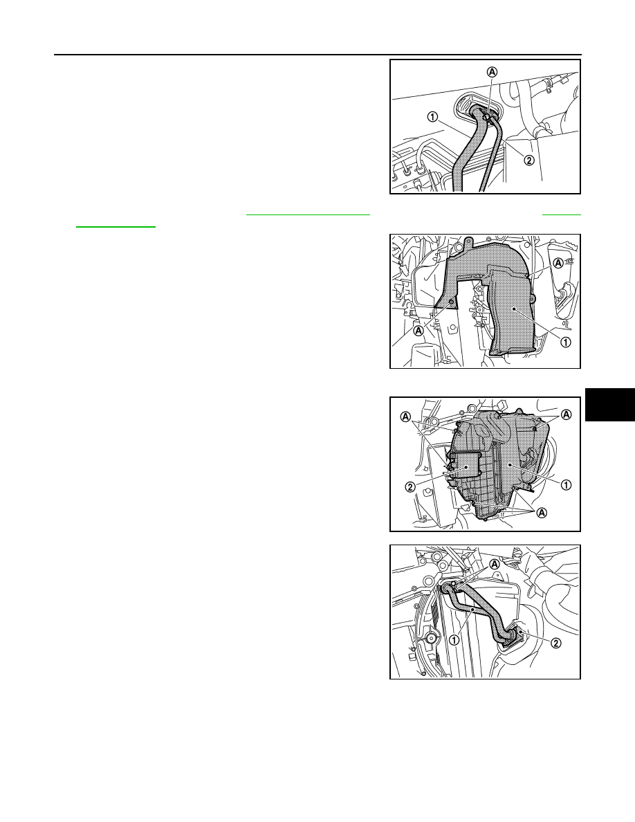
4.
Remove the mounting bolt (A), and then disconnect the low-
pressure pipe (1) and high-pressure pipe (2) from the expansion
valve.
CAUTION:
Cap or wrap the joint of the A/C piping and expansion valve
with suitable material such as vinyl tape to avoid the entry
of air.
5.
Remove the blower unit. Refer to
(WITHOUT 7 INCH DISPLAY) or
(WITH 7 INCH DISPLAY).
6.
Remove the mounting screws (A), and then remove the foot
duct assembly (RH) (1).
7.
Disconnect the air mix door motor (passenger side) connector.
8.
Remove the mounting screws (A), and then remove the heater &
cooling unit case cover (1) together with the air mix door motor
(passenger side) (2).
9.
Remove the mounting bolts (A), and then remove the evaporator
pipe assembly (1) and the expansion valve (2) from the evapo-
rator.
CAUTION:
Cap or wrap the joint of the A/C piping and evaporator with
suitable material such as vinyl tape to avoid the entry of air.
JPIIA0561ZZ
JPIIA0562ZZ
JPIIA0563ZZ
JPIIA0546ZZ
Нет комментариевНе стесняйтесь поделиться с нами вашим ценным мнением.
Текст