Nissan Murano Z51. Instruction — part 601

EC-412
< DTC/CIRCUIT DIAGNOSIS >
[VQ35DE]
P2127, P2128 APP SENSOR
4.
Also check harness for short to ground and short to power.
Is the inspection result normal?
YES
>> GO TO 7.
NO
>> Repair open circuit, short to ground or short to power in harness or connectors.
7.
CHECK APP SENSOR 2 INPUT SIGNAL CIRCUIT FOR OPEN AND SHORT
1.
Check the continuity between APP sensor harness connector and ECM harness connector.
2.
Also check harness for short to ground and short to power.
Is the inspection result normal?
YES
>> GO TO 8.
NO
>> Repair open circuit, short to ground or short to power in harness or connectors.
8.
CHECK APP SENSOR
EC-412, "Component Inspection"
Is the inspection result normal?
YES
>> GO TO 10.
NO
>> GO TO 9.
9.
REPLACE ACCELERATOR PEDAL ASSEMBLY
1.
Replace accelerator pedal assembly.
2.
EC-413, "Special Repair Requirement"
>> INSPECTION END
10.
CHECK INTERMITTENT INCIDENT
GI-39, "Intermittent Incident"
>> INSPECTION END
Component Inspection
INFOID:0000000005536835
1.
CHECK ACCELERATOR PEDAL POSITION SENSOR
1.
Reconnect all harness connectors disconnected.
2.
Turn ignition switch ON.
3.
Check the voltage between ECM harness connector terminals under the following conditions.
APP sensor
ECM
Continuity
Connector
Terminal
Connector
Terminal
E110
1
E16
100
Existed
APP sensor
ECM
Continuity
Connector
Terminal
Connector
Terminal
E110
6
E16
82
Existed
ECM
Condition
Voltage (V)
+
–
Connector
Terminal
Connector
Terminal
E16
81
(APP sensor 1 sig-
nal)
E16
84
(Sensor ground)
Accelerator pedal
Fully released
0.5 - 1.0
Fully depressed
4.2 - 4.8
82
(APP sensor 2 sig-
nal)
100
(Sensor ground)
Fully released
0.25 - 0.50
Fully depressed
2.0 - 2.5

P2127, P2128 APP SENSOR
EC-413
< DTC/CIRCUIT DIAGNOSIS >
[VQ35DE]
C
D
E
F
G
H
I
J
K
L
M
A
EC
N
P
O
Is the inspection result normal?
YES
>> INSPECTION END
NO
>> GO TO 2.
2.
REPLACE ACCELERATOR PEDAL ASSEMBLY
1.
Replace accelerator pedal assembly.
2.
Go to
EC-413, "Special Repair Requirement"
.
>> INSPECTION END
Special Repair Requirement
INFOID:0000000005536836
1.
PERFORM ACCELERATOR PEDAL RELEASED POSITION LEARNING
Refer to
EC-18, "ACCELERATOR PEDAL RELEASED POSITION LEARNING : Special Repair Requirement"
.
>> GO TO 2.
2.
PERFORM THROTTLE VALVE CLOSED POSITION LEARNING
EC-18, "THROTTLE VALVE CLOSED POSITION LEARNING : Special Repair Requirement"
>> GO TO 3.
3.
PERFORM IDLE AIR VOLUME LEARNING
EC-18, "IDLE AIR VOLUME LEARNING : Special Repair Requirement"
>> END
EC-414
< DTC/CIRCUIT DIAGNOSIS >
[VQ35DE]
P2135 TP SENSOR
P2135 TP SENSOR
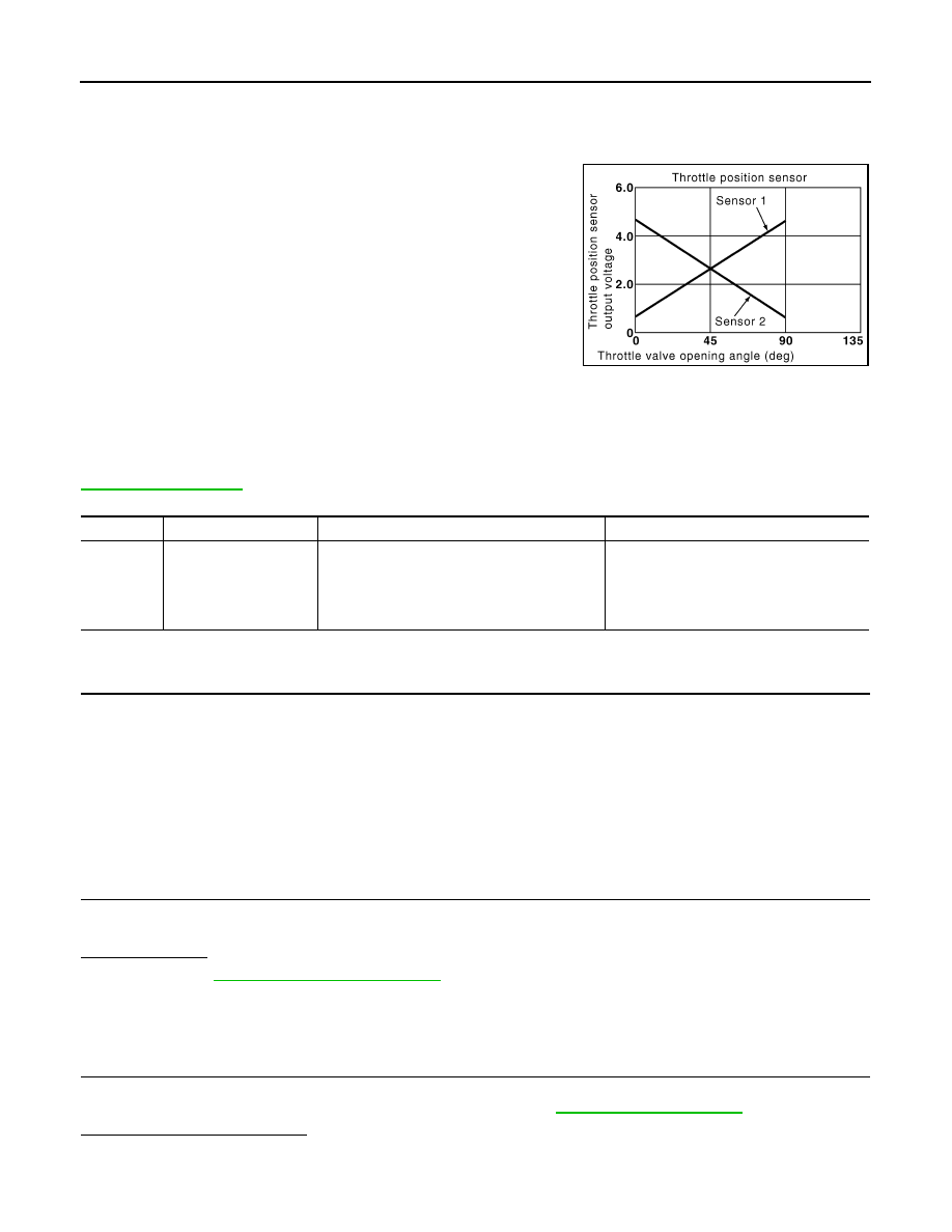
Description
INFOID:0000000005536837
Electric throttle control actuator consists of throttle control motor,
throttle position sensor, etc. The throttle position sensor responds to
the throttle valve movement.
The throttle position sensor has two sensors. These sensors are a
kind of potentiometers which transform the throttle valve position into
output voltage, and emit the voltage signals to the ECM. In addition,
these sensors detect the opening and closing speed of the throttle
valve and feed the voltage signals to the ECM. The ECM judges the
current opening angle of the throttle valve from these signals and the
ECM controls the throttle control motor to make the throttle valve
opening angle properly in response to driving condition.
DTC Logic
INFOID:0000000005536838
DTC DETECTION LOGIC
NOTE:
If DTC P2135 is displayed with DTC P0643, first perform the trouble diagnosis for DTC P0643. Refer to
DTC CONFIRMATION PROCEDURE
1.
PRECONDITIONING
If DTC Confirmation Procedure has been previously conducted, always perform the following before conduct-
ing the next test.
1.
Turn ignition switch OFF and wait at least 10 seconds.
2.
Turn ignition switch ON.
3.
Turn ignition switch OFF and wait at least 10 seconds.
TESTING CONDITION:
Before performing the following procedure, confirm that battery voltage is more than 8 V at idle.
>> GO TO 2.
2.
PERFORM DTC CONFIRMATION PROCEDURE
1.
Start engine and let it idle for 1 second.
2.
Check DTC.
Is DTC detected?
YES
>> Go to
NO
>> INSPECTION END
Diagnosis Procedure
INFOID:0000000005536839
1.
CHECK GROUND CONNECTION
1.
Turn ignition switch OFF.
2.
Check ground connection E38. Refer to Ground Inspection in
.
Is the inspection result normal?
YES
>> GO TO 2.
NO
>> Repair or replace ground connection.
PBIB0145E
DTC No.
Trouble diagnosis name
DTC detecting condition
Possible cause
P2135
Throttle position sensor
circuit range/perfor-
mance
Rationally incorrect voltage is sent to ECM
compared with the signals from TP sensor 1
and TP sensor 2.
• Harness or connector
(TP sensor 1 or 2 circuit is open or short-
ed.)
• Electric throttle control actuator
(TP sensor 1 or 2)

P2135 TP SENSOR
EC-415
< DTC/CIRCUIT DIAGNOSIS >
[VQ35DE]
C
D
E
F
G
H
I
J
K
L
M
A
EC
N
P
O
2.
CHECK THROTTLE POSITION SENSOR POWER SUPPLY CIRCUIT-I
1.
Disconnect electric throttle control actuator harness connector.
2.
Turn ignition switch ON.
3.
Check the voltage between electric throttle control actuator harness connector and ground.
Is the inspection result normal?
YES
>> GO TO 3.
NO
>> Repair open circuit, short to ground or short to power in harness or connectors.
3.
CHECK THROTTLE POSITION SENSOR GROUND CIRCUIT FOR OPEN AND SHORT
1.
Turn ignition switch OFF.
2.
Disconnect ECM harness connector.
3.
Check the continuity between electric throttle control actuator harness connector and ECM harness con-
nector.
4.
Also check harness for short to ground and short to power.
Is the inspection result normal?
YES
>> GO TO 4.
NO
>> Repair open circuit, short to ground or short to power in harness or connectors.
4.
CHECK THROTTLE POSITION SENSOR INPUT SIGNAL CIRCUIT FOR OPEN AND SHORT
1.
Check the continuity between electric throttle control actuator harness connector and ECM harness con-
nector.
2.
Also check harness for short to ground and short to power.
Is the inspection result normal?
YES
>> GO TO 5.
NO
>> Repair open circuit, short to ground or short to power in harness or connectors.
5.
CHECK THROTTLE POSITION SENSOR
EC-416, "Component Inspection"
Is the inspection result normal?
YES
>> GO TO 7.
NO
>> GO TO 6.
6.
REPLACE ELECTRIC THROTTLE CONTROL ACTUATOR
1.
Replace electric throttle control actuator.
2.
EC-416, "Special Repair Requirement"
>> INSPECTION END
7.
CHECK INTERMITTENT INCIDENT
GI-39, "Intermittent Incident"
.
Electric throttle control actuator
Ground
Voltage (V)
Connector
Terminal
F29
1
Ground
Approx. 5
Electric throttle control actuator
ECM
Continuity
Connector
Terminal
Connector
Terminal
F29
4
F8
36
Existed
Electric throttle control actuator
ECM
Continuity
Connector
Terminal
Connector
Terminal
F29
2
F8
37
Existed
3
38
Нет комментариевНе стесняйтесь поделиться с нами вашим ценным мнением.
Текст