Nissan Murano Z51. Instruction — part 243
AV
CAMERA CONTROL UNIT
AV-751
< ECU DIAGNOSIS INFORMATION >
[BOSE AUDIO WITH NAVIGATION]
C
D
E
F
G
H
I
J
K
L
M
B
A
O
P
CAMERA CONTROL UNIT
Reference Values
INFOID:0000000005528811
TERMINAL LAYOUT
PHYSICAL VALUES
JPNIA0007ZZ
Terminal
(Wire color)
Description
Condition
Reference value
(Approx.)
+
–
Signal name
Input/
Output
5
—
Shield
—
—
—
—
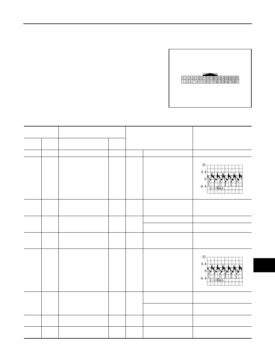
6
(B)
Ground
Camera image signal
Input
Ignition
switch
ON
when rear view camera im-
age is displayed.
7
(R/W)
Ground
Rear view camera ground
—
Ignition
switch
ON
—
0 V
8
(R/L)
Ground
Camera ON signal
Output
Ignition
switch
ON
R position.
6.0 V
Other than R position.
0 V
11
Ground
Shield (camera image
ground
—
Ignition
switch
ON
—
0 V
12
(B)
11
Camera image signal
Output
Ignition
switch
ON
when rear view camera im-
age is displayed.
14
(L)
Ground
Camera-connection recog-
nition signal
Output
Ignition
switch
ON
Connected to camera con-
trol unit connector.
0 V
Not connected to camera
control unit connector.
5.0 V
17
(BR)
—
AV communication signal
(L)
Input/
Output
—
—
—
18
(Y)
—
AV communication signal
(H)
Input/
Output
—
—
—
SKIB2251J
SKIB2251J
AV-752
< ECU DIAGNOSIS INFORMATION >
[BOSE AUDIO WITH NAVIGATION]
CAMERA CONTROL UNIT
19
(GR)
—
AV communication signal
(L)
Input/
Output
—
—
—
20
(G)
—
AV communication signal
(H)
Input/
Output
—
—
—
22
(R)
Ground
Reverse signal
Input
Ignition
switch
ON
R position.
12.0 V
Other than R position.
0 V
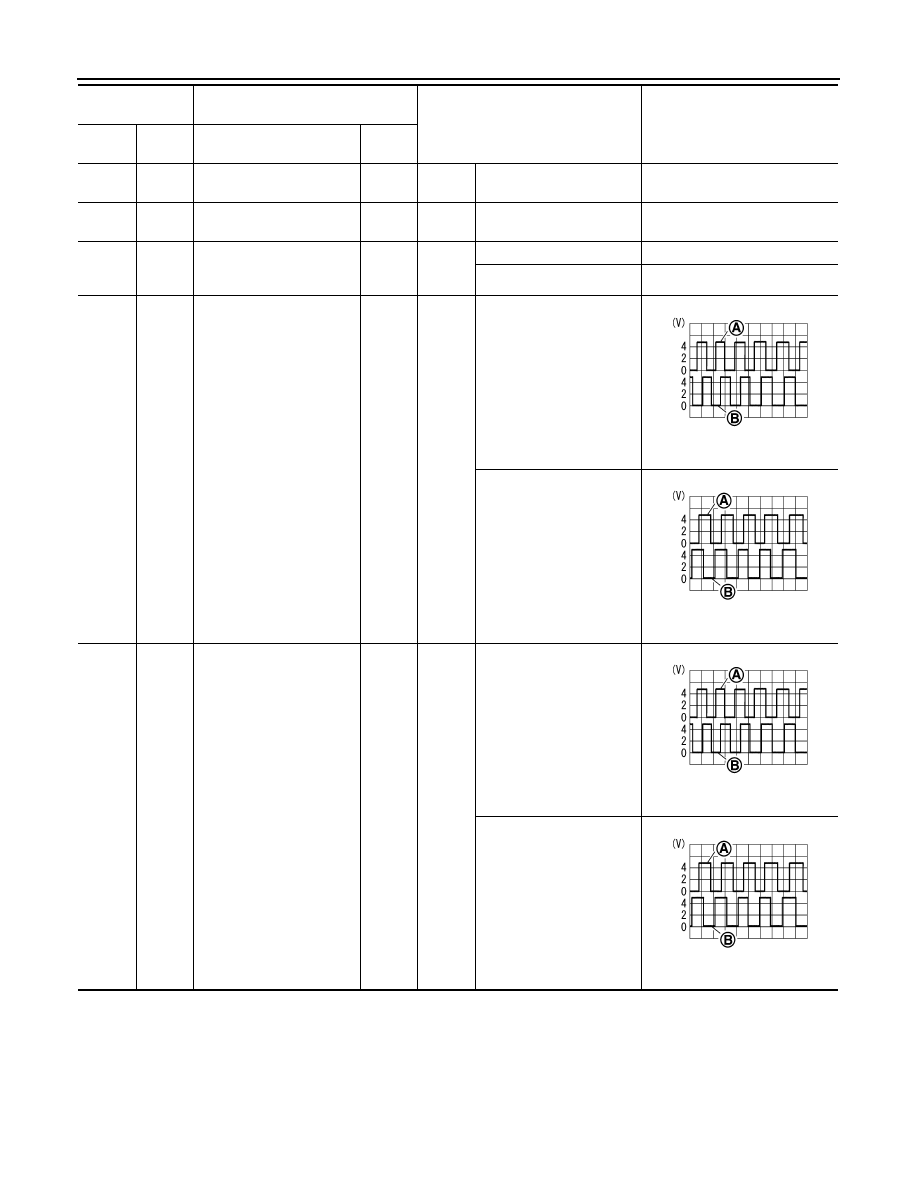
23
(G)
Ground
Sensor signal 1
Input
Ignition
switch
ON
Turn the steering to the
right.
A: Sensor signal 1
B: Sensor signal 2
Turn the steering to the left.
A: Sensor signal 1
B: Sensor signal 2
24
(SB)
Ground
Sensor signal 2
Input
Ignition
switch
ON
Turn the steering to the
right.
A: Sensor signal 1
B: Sensor signal 2
Turn the steering to the left.
A: Sensor signal 1
B: Sensor signal 2
Terminal
(Wire color)
Description
Condition
Reference value
(Approx.)
+
–
Signal name
Input/
Output
SKIB3827E
SKIB3828E
SKIB3827E
SKIB3828E
AV
CAMERA CONTROL UNIT
AV-753
< ECU DIAGNOSIS INFORMATION >
[BOSE AUDIO WITH NAVIGATION]
C
D
E
F
G
H
I
J
K
L
M
B
A
O
P
Wiring Diagram - BOSE AUDIO WITH NAVIGATION SYSTEM -
INFOID:0000000005528812
NOTE:
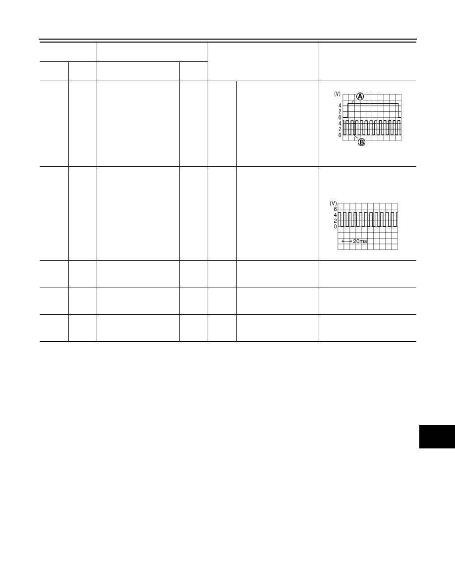
25
(O)
Ground
Sensor signal 3
Input
Ignition
switch
ON
Turn the steering around
the neutral position.
A: Sensor signal 3
B: Sensor signal 1
26
(BR)
Ground
Vehicle speed signal
(8-pulse)
Input
Ignition
switch
ON
When vehicle speed is ap-
prox. 40 km/h (25 MPH).
NOTE:
Maximum voltage may be 12 V
due to specifications (connected
units).
30
(GR)
Ground
ACC power supply
Input
Ignition
switch
ACC
—
Battery voltage
31
(B)
Ground
Ground
—
Ignition
switch
ON
—
0 V
32
(V)
Ground
Battery power supply
Input
Ignition
switch
OFF
—
Battery voltage
Terminal
(Wire color)
Description
Condition
Reference value
(Approx.)
+
–
Signal name
Input/
Output
SKIB3829E
SKIA6649J

AV-754
< ECU DIAGNOSIS INFORMATION >
[BOSE AUDIO WITH NAVIGATION]
CAMERA CONTROL UNIT
In this section, PRESET SWITCH and MULTIFUNCTION SWITCH are written as the MULTIFUNCTION
SWITCH.
JCNWM1838GB
Нет комментариевНе стесняйтесь поделиться с нами вашим ценным мнением.
Текст