Nissan Murano Z51. Instruction — part 1162
RAX-10
< PREPARATION >
[AWD]
PREPARATION
PREPARATION
PREPARATION
Commercial Service Tool
INFOID:0000000005514290
Tool name
Description
Power tool
Loosening bolts and nuts
PBIC0190E
REAR WHEEL HUB AND HOUSING
RAX-11
< PERIODIC MAINTENANCE >
[AWD]
C
E
F
G
H
I
J
K
L
M
A
B
RAX
N
O
P
PERIODIC MAINTENANCE
REAR WHEEL HUB AND HOUSING
Inspection
INFOID:0000000005514291
MOUNTING INSPECTION
Make sure the mounting conditions (looseness, back lash) of each component and component conditions
(wear, damage) are normal.
WHEEL BEARING INSPECTION
• Move wheel hub and bearing assembly in the axial direction by hand. Make sure there is no looseness of
wheel bearing.
• Rotate wheel hub and bearing assembly and make sure there is no unusual noise or other irregular condi-
tions. If there is any of irregular conditions, replace wheel hub and bearing assembly.
Standard
Axial end play
: Refer to
RAX-12
< PERIODIC MAINTENANCE >
[AWD]
REAR DRIVE SHAFT
REAR DRIVE SHAFT
Inspection
INFOID:0000000005514292
• Check drive shaft mounting point and joint for looseness and other damage.
• Check boot for cracks and other damage.
CAUTION:
Replace entire drive shaft assembly when noise or vibration occurs from drive shaft.
REAR WHEEL HUB AND HOUSING
RAX-13
< REMOVAL AND INSTALLATION >
[AWD]
C
E
F
G
H
I
J
K
L
M
A
B
RAX
N
O
P
REMOVAL AND INSTALLATION
REAR WHEEL HUB AND HOUSING
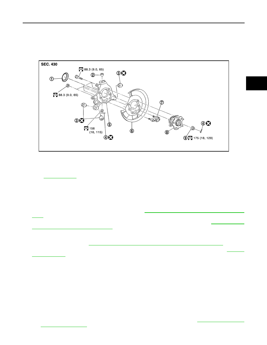
Exploded View
INFOID:0000000005514293
Removal and Installation
INFOID:0000000005514294
REMOVAL
1.
Remove tires with power tool.
2.
Remove wheel sensor and sensor harness. Refer to
BRC-111, "REAR WHEEL SENSOR : Exploded
.
3.
Remove caliper assembly. Hang caliper assembly not to interfere with work. Refer to
CALIPER ASSEMBLY : Exploded View"
.
CAUTION:
Never depress brake pedal while caliper assembly is removed.
4.
Remove disc rotor. Refer to
BR-43, "BRAKE CALIPER ASSEMBLY : Removal and Installation"
.
5.
Remove cotter pin, then loosen suspension arm mounting nut of axle housing. Refer to
6.
Remove cotter pin, and then loosen wheel hub lock nut with power tool.
7.
Patch wheel hub lock nut with a piece of wood. Hammer the wood to disengage wheel hub and bearing
assembly from drive shaft. Remove the wheel hub lock nut.
CAUTION:
• Never place drive shaft joint at an extreme angle. Also be careful not to overextend slide joint.
• Never allow drive shaft to hang down without support for housing (or joint sub-assembly), shaft
and the other parts.
NOTE:
Use suitable puller, if wheel hub and bearing assembly and drive shaft cannot be separated even after
performing the above procedure.
8.
Remove wheel hub and bearing assembly.
9.
Remove parking brake shoe and parking brake cable from back plate. Refer to
1.
Hub cap
2.
Ball seat
3.
Bushing
4.
Cotter pin
5.
Axle housing
6.
Back plate
7.
Anchor block
8.
Wheel hub and bearing assembly
9.
Wheel hub lock nut
Refer to
JPDIG0135GB
Нет комментариевНе стесняйтесь поделиться с нами вашим ценным мнением.
Текст