Nissan Murano Z51. Instruction — part 657
EM-100
< UNIT DISASSEMBLY AND ASSEMBLY >
CAMSHAFT
1.
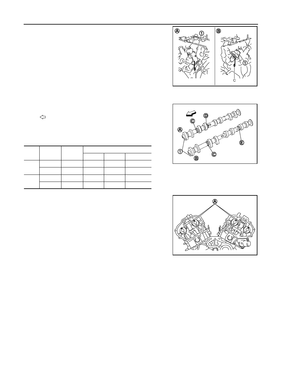
Install timing chain tensioners (secondary) (1) on both sides of
cylinder head.
• Install timing chain tensioner (secondary) with its stopper pin
(C) attached.
• Install timing chain tensioner (secondary) with sliding part fac-
ing downward on cylinder head (bank 1), and with sliding part
facing upward on cylinder head (bank 2).
2.
Install valve lifters.
• Install it in the original position.
3.
Install camshafts.
• Follow your identification marks made during removal, or fol-
low the identification marks that are present on new camshafts
for proper placement and direction.
• Install camshaft so dowel pin (A) on front end face are posi-
tioned as shown in the figure. (No. 1 cylinder TDC on its com-
pression stroke)
NOTE:
Though camshaft does not stop at the portion as shown in the
figure, for the placement of cam nose, it is generally accepted
camshaft is placed for the same direction of the figure.
4.
Install camshaft brackets.
• Remove foreign material completely from camshaft bracket backside and from cylinder head installation
face.
A
: Bank 1
B
: Bank 2
JPBIA0121ZZ
: Engine front
Bank
INT/EXH
Dowel pin
(1)
Paint marks
M1 (D)
M2 (E)
M3 (C)
1
EXH (B)
Yes
No
Light blue
Light blue
INT (A)
Yes
Pink
No
Light blue
2
INT (A)
Yes
Pink
No
Light blue
EXH (B)
Yes
No
Light blue
Light blue
JPBIA1749ZZ
JPBIA2368ZZ
CAMSHAFT
EM-101
< UNIT DISASSEMBLY AND ASSEMBLY >
C
D
E
F
G
H
I
J
K
L
M
A
EM
N
P
O
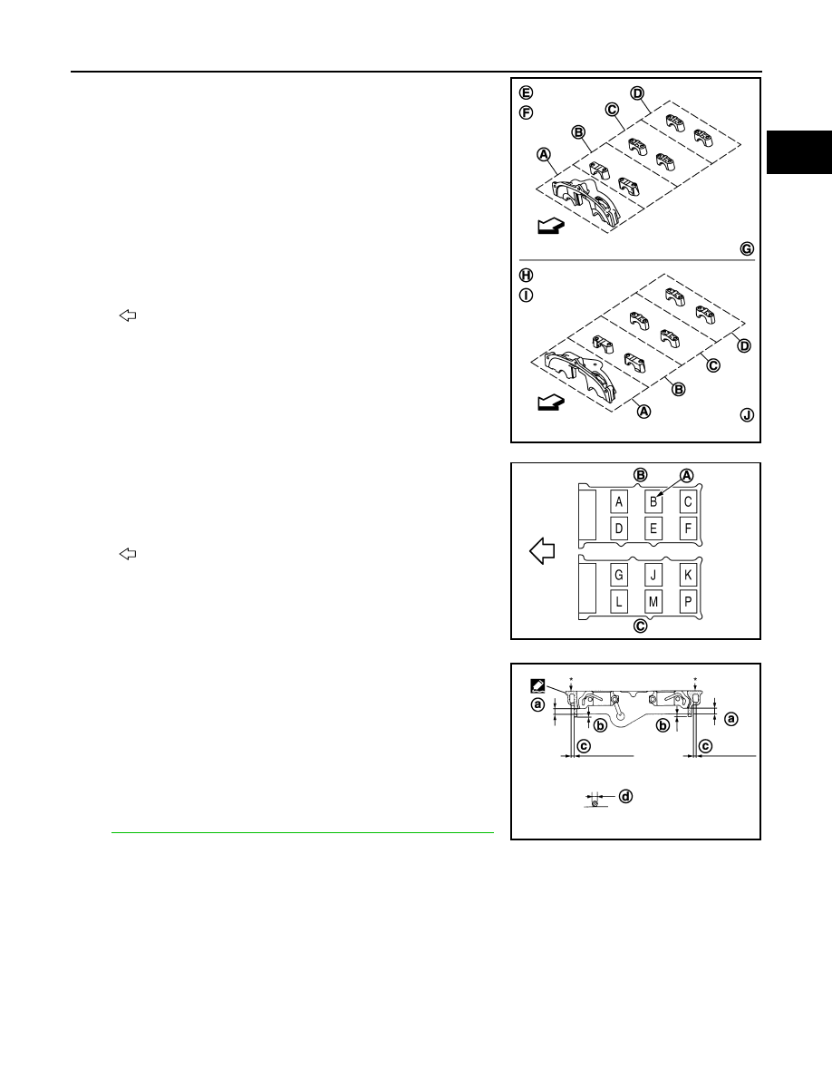
• Install camshaft bracket in original position and direction as
shown in the figure.
• Install camshaft brackets (No. 2 to 4) aligning the stamp marks
(A) as shown in the figure.
NOTE:
There are no identification marks indicating left and right for
camshaft bracket (No. 1).
• Apply liquid gasket to mating surface of camshaft bracket (No.
1) as shown on bank 1 and bank 2.
Use Genuine RTV Silicone Sealant or equivalent. Refer to
GI-18, "Recommended Chemical Products and Sealants"
.
A
: No. 1
B
: No. 2
C
: No. 3
D
: No. 4
E
: Bank 1
F
: Exhaust side
G
: Intake side
H
: Bank 2
I
: Intake side
J
: Exhaust side
: Engine front
JPBIA0258ZZ
B
: Bank 1
C
: Bank 2
: Engine front
JPBIA0272ZZ
a
: 8.5 mm (0.335 in)
b
: 2 mm (0.08 in)
c
: Clearance 5 mm (0.20 in)
d
:
φ
2.0 - 2.3 mm (0.079 - 0.091 in)
*
: Apply liquid gasket to rear timing chain case side
JPBIA0255ZZ
EM-102
< UNIT DISASSEMBLY AND ASSEMBLY >
CAMSHAFT
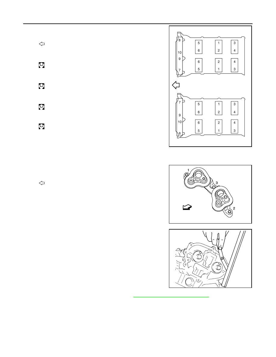
5.
Tighten camshaft bracket bolts in the following steps, in numeri-
cal order as shown in the figure.
a.
Tighten No. 7 to 10 in order as shown.
b.
Tighten No. 1 to 6 in order as shown.
c.
Tighten No. 1 to 10 in numerical order as shown.
d.
Tighten No. 1 to 10 in numerical order as shown.
CAUTION:
After tightening mounting bolts of camshaft brackets (No.
1), be sure to wipe off excessive liquid gasket from the
parts list below.
• Mating surface of rocker cover
• Mating surface of rear timing chain case
6.
Tighten camshaft sensor bracket bolts in numerical order as
shown in the figure.
NOTE:
The order of tightening bolts in the same for bank 1 and bank 2.
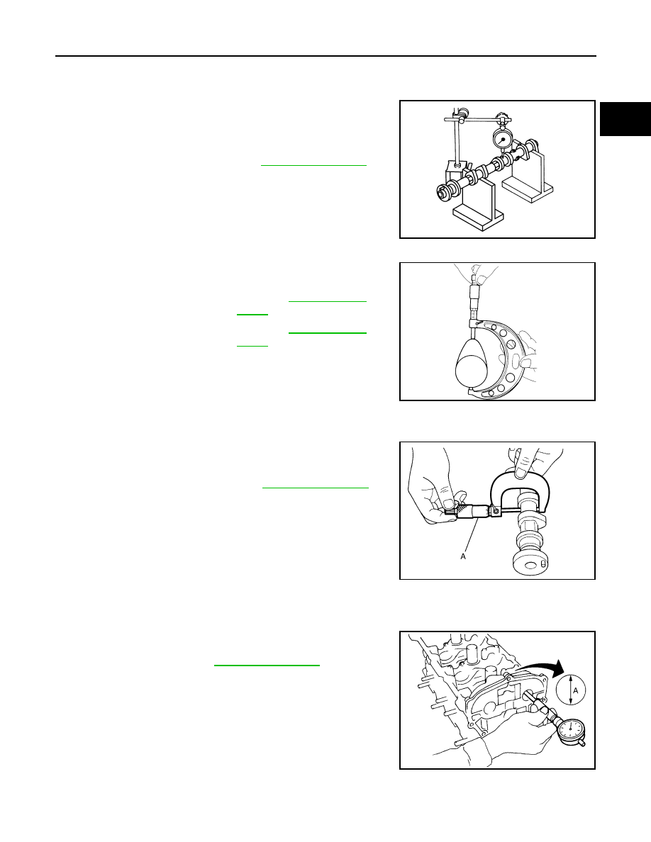
7.
Measure difference in levels between front end faces of cam-
shaft bracket (No. 1) and cylinder head.
• Measure two positions (both intake and exhaust side) for a
single bank.
• If the measured value is out of the standard, reinstall camshaft
bracket (No. 1).
8.
Inspect and adjust the valve clearance. Refer to
EM-22, "Inspection and Adjustment"
.
9.
Install in the reverse order of removal after this step.
Inspection
INFOID:0000000005515963
INSPECTION AFTER REMOVAL
Camshaft Runout
1.
Put V-block on precise flat table, and support No. 2 and 4 journals of camshaft.
: Engine front
: 1.96 N·m (0.20 kg-m, 1 ft-lb)
: 1.96 N·m (0.20 kg-m, 1 ft-lb)
: 5.88 N·m (0.60 kg-m, 4 ft-lb)
: 10.4 N·m (1.1 kg-m, 8 ft-lb)
: Engine front
JPBIA0257ZZ
JPBIA1960ZZ
Standard
:
−
0.14 to 0.14 mm (
−
0.0055 to 0.0055 in)
EMQ0044D
CAMSHAFT
EM-103
< UNIT DISASSEMBLY AND ASSEMBLY >
C
D
E
F
G
H
I
J
K
L
M
A
EM
N
P
O
CAUTION:
Never support No. 1 journal (on the side of camshaft sprocket) because it has a different diameter
from the other three locations.
2.
Set a dial indicator vertically to No. 3 journal.
3.
Turn camshaft to one direction with hands, and measure the
camshaft runout on a dial indicator. (Total indicator reading)
4.
If it exceeds the limit, replace camshaft.
Camshaft Cam Height
1.
Measure the camshaft cam height with a micrometer.
2.
If wear exceeds the limit, replace camshaft.
Camshaft Journal Oil Clearance
CAMSHAFT JOURNAL DIAMETER
• Measure the outer diameter of camshaft journal with a micrometer
(A).
CAMSHAFT BRACKET INNER DIAMETER
• Tighten camshaft bracket bolt with the specified torque. Refer to “INSTALLATION” for the tightening proce-
dure.
• Measure inner diameter (A) of camshaft bracket with a bore gauge.
CAMSHAFT JOURNAL OIL CLEARANCE
• (Oil clearance) = (Camshaft bracket inner diameter) – (Camshaft journal diameter).
Standard and limit
: Refer to
.
PBIC0929E
Standard cam height
: Refer to
.
(Intake and exhaust)
Cam wear limit
: Refer to
.
EMQ0072D
Standard and limit
: Refer to
JPBIA0122ZZ
Standard
: Refer to
.
PBIC1645E
Нет комментариевНе стесняйтесь поделиться с нами вашим ценным мнением.
Текст