Nissan Murano Z51. Instruction — part 642
EM-40
< REMOVAL AND INSTALLATION >
EXHAUST MANIFOLD AND THREE WAY CATALYST
8.
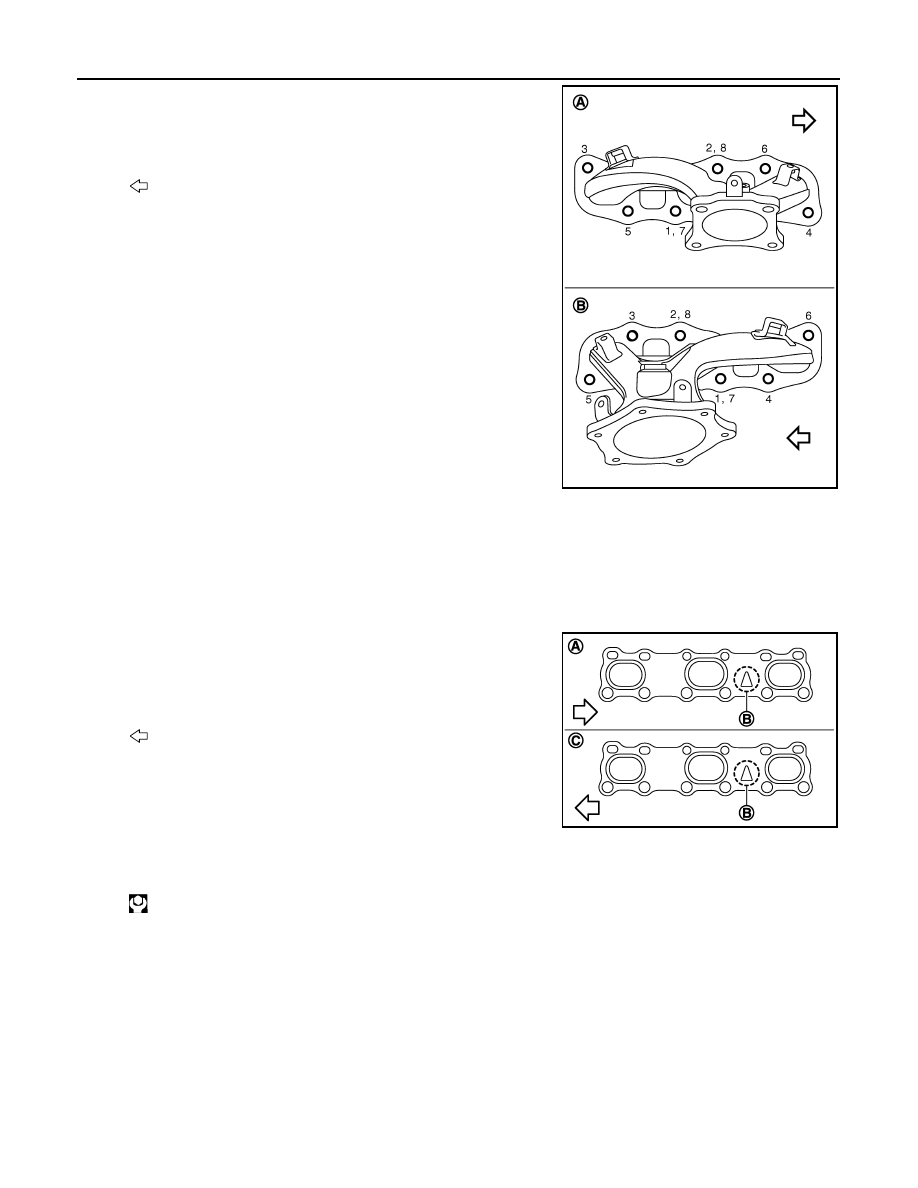
Loosen mounting nuts in the reverse order as shown in the fig-
ure to remove exhaust manifolds (bank 1 and bank 2).
NOTE:
Disregard No. 7 and 8 when loosing.
9.
Remove gaskets.
CAUTION:
Cover engine openings to avoid entry of foreign materials.
INSTALLATION
Note the following, and install in the reverse order of removal.
Exhaust Manifold Gasket
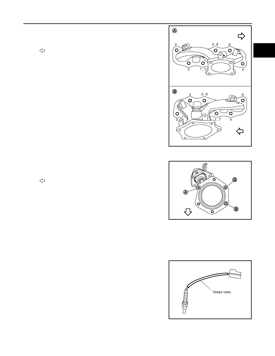
Install in the direction indicated in the figure.
Exhaust Manifold
• If stud bolts were removed, install them and tighten to the torque specified below.
A
: Bank 1
B
: Bank 2
: Engine front
JPBIA1633ZZ
A
: Bank 1
B
: Triangle press
C
: Bank 2
: Engine front
PBIC4954E
: 15.4 N·m (1.6 kg-m, 11 ft-lb)
EXHAUST MANIFOLD AND THREE WAY CATALYST
EM-41
< REMOVAL AND INSTALLATION >
C
D
E
F
G
H
I
J
K
L
M
A
EM
N
P
O
• Tighten mounting nuts in numerical order as shown in the figure.
NOTE:
No. 7 and 8 mean double tightening of nuts No. 1 and 2.
Three Way Catalyst (bank 2) Flange Bolt Type
1.
Temporarily tighten upper side bolts (B) and lower side bolt (A)
shown in the figure.
2.
Tighten the upper side bolts (B) shown in the figure. (specified
torque)
3.
Tighten all the lower side bolts [the other four except (B)]. (spec-
ified torque)
Three Way Catalyst Supports
1.
Temporarily tighten three way catalyst support mounting bolts.
2.
Tighten three way catalyst support mounting bolts to oil pan (upper).
3.
Tighten three way catalyst support mounting bolts to three way catalyst.
Air Fuel Ratio Sensor 1 and Heated Oxygen Sensor 2
• Install air fuel ratio sensor 1 and heated oxygen sensor 2 in the original position.
• Install referring the following if the installation positions cannot be
identified.
CAUTION:
• Before installing a new air fuel ratio sensor and a new heated
oxygen sensor, clean exhaust system threads using oxygen
sensor thread cleaner (commercial service tool: J-43897-18 or
J-43897-12) and apply anti-seize lubricant (commercial ser-
vice tool).
• Never over torque air fuel ratio sensor and heated oxygen sensor. Doing so may cause damage to air
fuel ratio sensor and heated oxygen sensor, resulting in “MIL” coming on.
A
: Bank 1
B
: Bank 2
: Engine front
JPBIA1633ZZ
: Engine front
JPBIA2709ZZ
Glass tube color
Air fuel ratio sensor 1
: Black
Heated oxygen sensor 2
: White
PBIC2652E
EM-42
< REMOVAL AND INSTALLATION >
EXHAUST MANIFOLD AND THREE WAY CATALYST
Inspection
INFOID:0000000005515938
INSPECTION AFTER REMOVAL
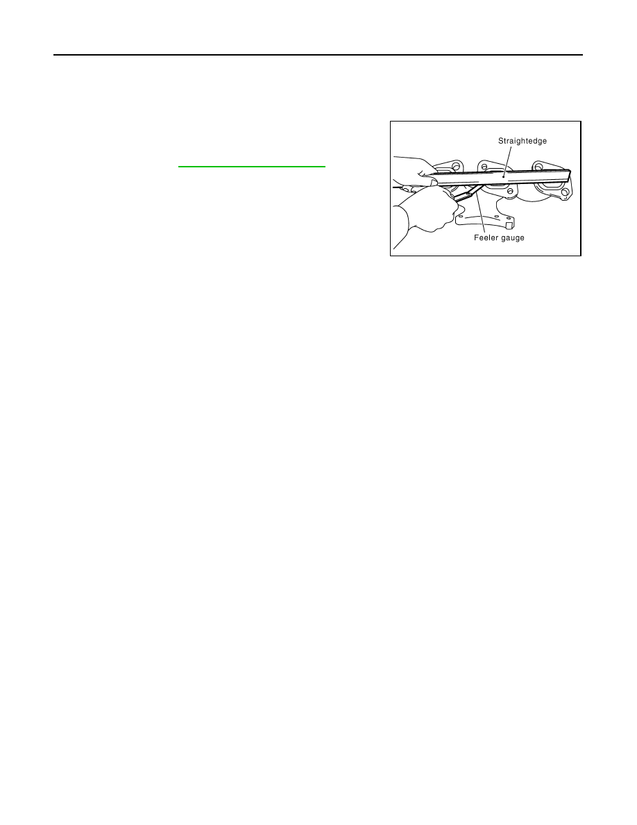
Surface Distortion
• Check the surface distortion of the exhaust manifold mating sur-
face with a straightedge and a feeler gauge.
• If it exceeds the limit, replace exhaust manifold.
Limit
: Refer to
.
PBIC1173E
OIL PAN AND OIL STRAINER
EM-43
< REMOVAL AND INSTALLATION >
C
D
E
F
G
H
I
J
K
L
M
A
EM
N
P
O
OIL PAN AND OIL STRAINER
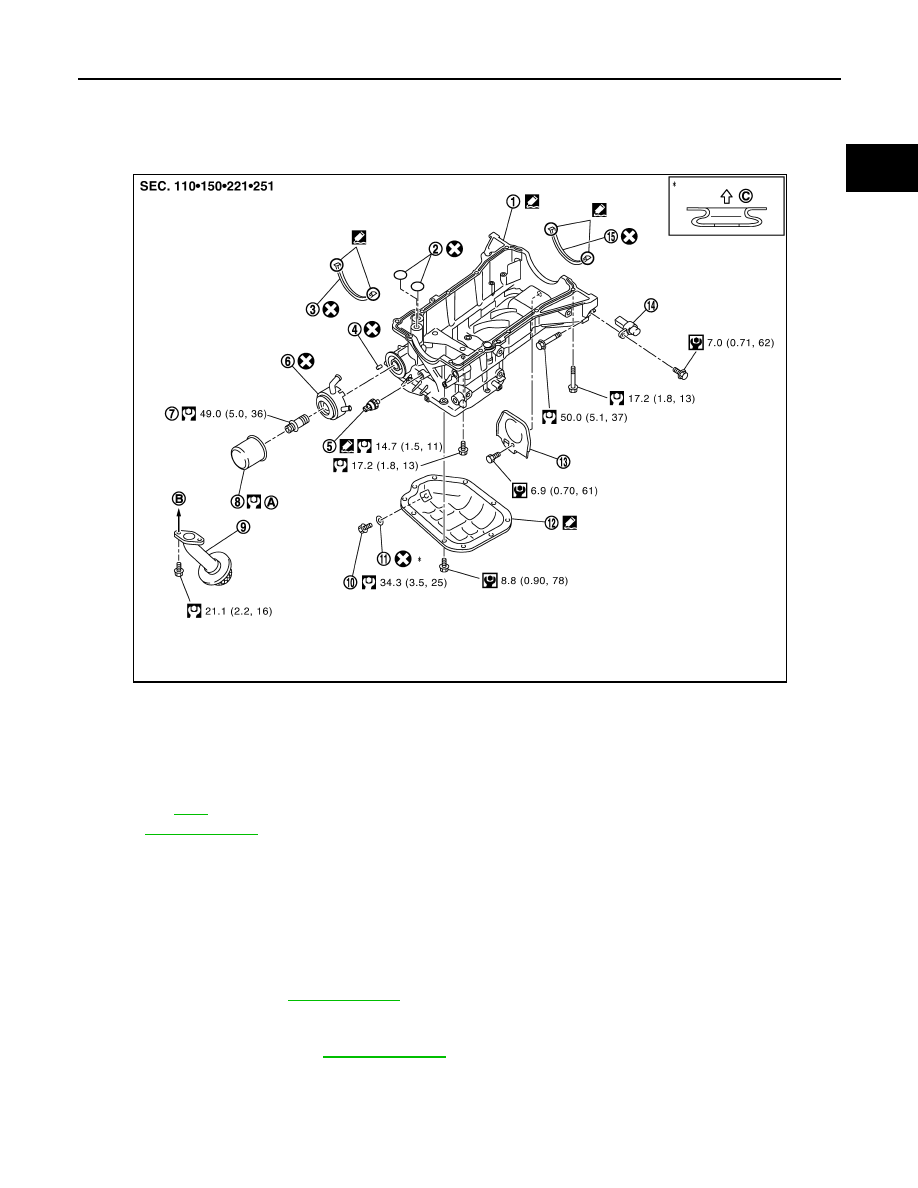
Exploded View
INFOID:0000000005515939
Removal and Installation
INFOID:0000000005515940
REMOVAL
CAUTION:
To avoid the danger of being scalded, never drain engine oil when the engine is hot.
NOTE:
When removing oil pan (lower) or oil strainer only, take step 1 then step 19 and 20.
1.
Drain engine oil. Refer to
.
CAUTION:
Never spill engine oil on drive belt.
2.
Drain engine coolant. Refer to
.
CAUTION:
Never spill engine coolant on drive belt.
3.
Remove following parts:
• Front road wheel and tires (RH and LH).
1.
Oil pan (upper)
2.
O-ring
3.
Oil pan gasket (front)
4.
Relief valve
5.
Oil pressure switch
6.
Oil cooler
7.
Connector bolt
8.
Oil filter
9.
Oil strainer
10. Drain plug
11.
Drain plug washer
12. Oil pan (lower)
13. Rear plate cover
14. Crankshaft position sensor (POS)
15. Oil pan gasket (rear)
A.
Refer to
B.
To oil pump
C.
Oil pan side
Refer to
for symbols in the figure.
JPBIA1636GB
Нет комментариевНе стесняйтесь поделиться с нами вашим ценным мнением.
Текст