Nissan Murano Z51. Instruction — part 79

AV
U1310 AV CONTROL UNIT
AV-95
< DTC/CIRCUIT DIAGNOSIS >
[BOSE AUDIO WITHOUT NAVIGATION]
C
D
E
F
G
H
I
J
K
L
M
B
A
O
P
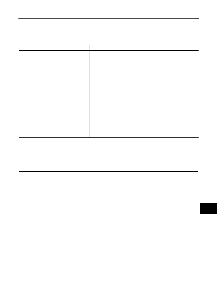
U1310 AV CONTROL UNIT
Description
INFOID:0000000005528486
Replace the AV control unit if this DTC is displayed. Refer to
DTC Logic
INFOID:0000000005528487
Part name
Description
AV CONTROL UNIT
• It is the master unit of the MULTI AV system, and it is connected to each control
unit by communication. It operates each system according to communication
signals from the AV control unit.
• AV control unit includes audio function and vehicle information function.
• It is connected to ECM, A/C auto amp. and combination meter via CAN com-
munication to obtain necessary information for the vehicle information function.
• It is connected to BCM via CAN communication transmitting/receiving for the
vehicle settings function.
• It inputs the illumination signals that are required for the display dimming con-
trol.
• It inputs the signals for driving status recognition (vehicle speed, reverse and
parking brake).
• The camera image signal is input from the camera control unit. The AV control
unit outputs camera image signal to the front display unit.
• BOSE amp. ON signal and sound signal are transmitted to BOSE amp.
• Power (signal VCC and inverter VCC) is transmitted to front display.
Without DVD entertainment system
• Auxiliary image and auxiliary sound signals are input from the auxiliary input
jacks.
With DVD entertainment system
• Composite image signal (auxiliary and DVD images) is input from the video
distributor.
• Sound signal (DVD and auxiliary sounds) is input from the DVD player.
DTC
Display contents of
CONSULT-III
DTC Detection Condition
Action to take
U1310
CONTROL UNIT (AV)
[U1310]
An initial diagnosis error is detected in AV communication
circuit.
Replace AV control unit.

AV-96
< DTC/CIRCUIT DIAGNOSIS >
[BOSE AUDIO WITHOUT NAVIGATION]
U1200 AV CONTROL UNIT
U1200 AV CONTROL UNIT
Description
INFOID:0000000005528488
Replace the AV control unit if this DTC is displayed. Refer to
.
DTC Logic
INFOID:0000000005528489
Part name
Description
AV CONTROL UNIT
• It is the master unit of the MULTI AV system, and it is connected to each control
unit by communication. It operates each system according to communication
signals from the AV control unit.
• AV control unit includes audio function and vehicle information function.
• It is connected to ECM, A/C auto amp. and combination meter via CAN com-
munication to obtain necessary information for the vehicle information function.
• It is connected to BCM via CAN communication transmitting/receiving for the
vehicle settings function.
• It inputs the illumination signals that are required for the display dimming con-
trol.
• It inputs the signals for driving status recognition (vehicle speed, reverse and
parking brake).
• The camera image signal is input from the camera control unit. The AV control
unit outputs camera image signal to the front display unit.
• BOSE amp. ON signal and sound signal are transmitted to BOSE amp.
• Power (signal VCC and inverter VCC) is transmitted to front display.
Without DVD entertainment system
• Auxiliary image and auxiliary sound signals are input from the auxiliary input
jacks.
With DVD entertainment system
• Composite image signal (auxiliary and DVD images) is input from the video
distributor.
• Sound signal (DVD and auxiliary sounds) is input from the DVD player.
DTC
Display contents of
CONSULT-III
DTC Detection Condition
Action to take
U1200
Cont Unit
FLASH- ROM
[U1200]
An internal malfunction is detected in AV control unit
(FLASH-ROM).
Replace AV control unit.
AV
U1216 AV CONTROL UNIT
AV-97
< DTC/CIRCUIT DIAGNOSIS >
[BOSE AUDIO WITHOUT NAVIGATION]
C
D
E
F
G
H
I
J
K
L
M
B
A
O
P
U1216 AV CONTROL UNIT
Description
INFOID:0000000005528490
Replace the AV control unit if this DTC is displayed. Refer to
DTC Logic
INFOID:0000000005528491
Part name
Description
AV CONTROL UNIT
• It is the master unit of the MULTI AV system, and it is connected to each control
unit by communication. It operates each system according to communication
signals from the AV control unit.
• AV control unit includes audio function and vehicle information function.
• It is connected to ECM, A/C auto amp. and combination meter via CAN com-
munication to obtain necessary information for the vehicle information function.
• It is connected to BCM via CAN communication transmitting/receiving for the
vehicle settings function.
• It inputs the illumination signals that are required for the display dimming con-
trol.
• It inputs the signals for driving status recognition (vehicle speed, reverse and
parking brake).
• The camera image signal is input from the camera control unit. The AV control
unit outputs camera image signal to the front display unit.
• BOSE amp. ON signal and sound signal are transmitted to BOSE amp.
• Power (signal VCC and inverter VCC) is transmitted to front display.
Without DVD entertainment system
• Auxiliary image and auxiliary sound signals are input from the auxiliary input
jacks.
With DVD entertainment system
• Composite image signal (auxiliary and DVD images) is input from the video
distributor.
• Sound signal (DVD and auxiliary sounds) is input from the DVD player.
DTC
Display contents of
CONSULT-III
DTC Detection Condition
Action to take
U1216
CAN CONT
[U1216]
Internal malfunction of AV control unit (CAN controller) is
detected.
Replace AV control unit.
AV-98
< DTC/CIRCUIT DIAGNOSIS >
[BOSE AUDIO WITHOUT NAVIGATION]
U1243 DISPLAY UNIT
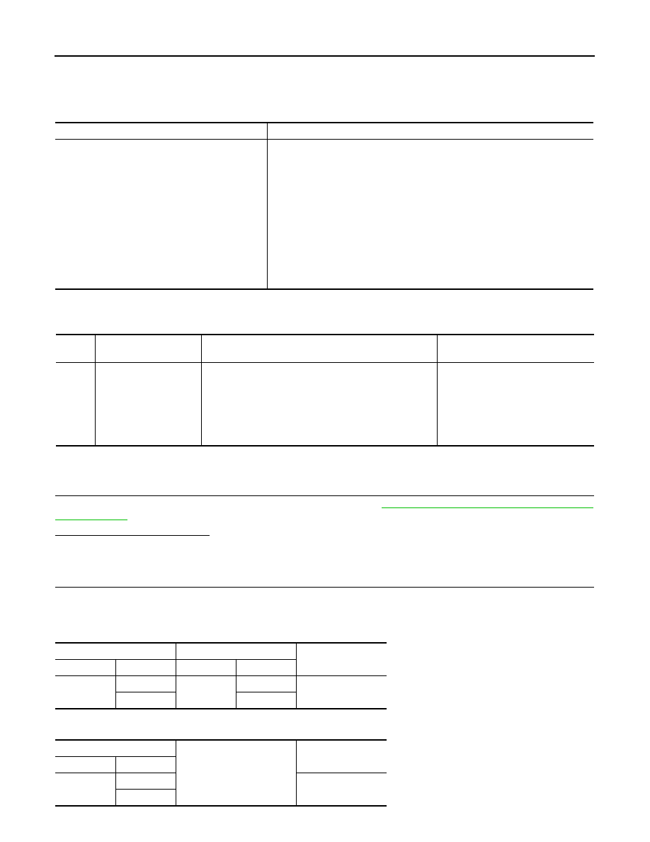
U1243 DISPLAY UNIT
Description
INFOID:0000000005528492
DTC Logic
INFOID:0000000005528493
Diagnosis Procedure
INFOID:0000000005528494
1.
CHECK DISPLAY UNIT POWER SUPPLY AND GROUND CIRCUIT
Check front display unit power supply and ground circuit. Refer to
AV-107, "FRONT DISPLAY UNIT : Diagno-
Is the inspection result normal?
YES
>> GO TO 2.
NO
>> Repair malfunctioning parts.
2.
CHECK CONTINUITY COMMUNICATION CIRCUIT
1.
Turn ignition switch OFF.
2.
Disconnect front display unit connector and AV control unit connector.
3.
Check continuity between front display unit harness connector and AV control unit harness connector.
4.
Check continuity between front display unit harness connector and ground.
Part name
Description
FRONT DISPLAY UNIT
• Front display image is controlled by the serial communication from AV control
unit.
• It receives the power (signal VCC and inverter VCC) from the AV control unit
and operates.
• RGB image signal is input from AV control unit (RGB, RGB area and RGB syn-
chronizing).
• Synchronizing signal (HP, VP) is output to AV control unit.
• Camera image signal is input from AV control unit.
Without DVD entertainment system
• Auxiliary image signal is input from AV control unit.
With DVD entertainment system
• Composite image signal (auxiliary and DVD images) is input from the AV con-
trol unit.
DTC
Display contents of
CONSULT-III
DTC Detection Condition
Possible causes
U1243
FRONT DISP CONN
[U1243]
When either one of the following items are detected:
• front display unit power supply and ground circuits are
malfunctioning.
• serial communication circuits between AV control unit
and front display unit are malfunctioning.
• serial communication signal between AV control unit
and front display unit is malfunctioning.
• Front display unit power supply and
ground circuits.
• Serial communication circuits be-
tween AV control unit and front dis-
play unit.
Front display unit
AV control unit
Continuity
Connector
Terminals
Connector
Terminals
M49
11
M129
56
Existed
22
44
Front display unit
Ground
Continuity
Connector
Terminals
M49
11
Not existed
22
Нет комментариевНе стесняйтесь поделиться с нами вашим ценным мнением.
Текст