Nissan Murano Z51. Instruction — part 497
DLN-122
< UNIT DISASSEMBLY AND ASSEMBLY >
[REAR FINAL DRIVE: R145]
DRIVE PINION
3.
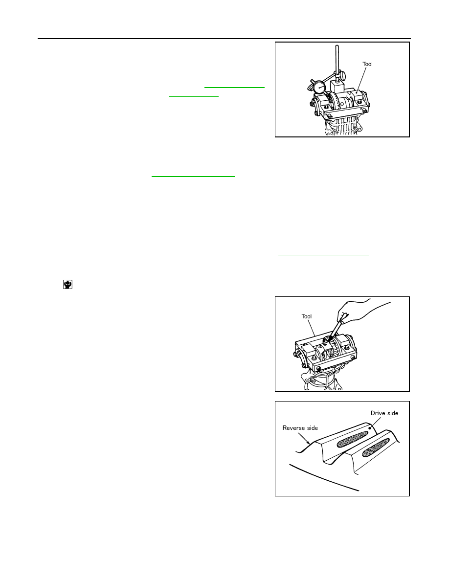
Fit a dial indicator to the drive gear back face.
4.
Rotate the drive gear to measure runout.
• If the runout is outside of the repair limit, check drive gear
assembly condition; foreign material may be caught between
drive gear and differential case, or differential case or drive
gear may be deformed, etc.
CAUTION:
Replace drive gear and drive pinion as a set.
TOOTH CONTACT
1.
Remove rear cover. Refer to
.
2.
Following the procedure below, install a dummy cover set [SST: KV381086S1 (
—
)] to gear car-
rier.
a.
Set dummy cover shims [SST: KV38108630 (
—
)] to the right and left side bearing adjusting
shims.
b.
Temporarily tighten dummy cover [SST: 38108620 (
—
)] to gear carrier.
c.
Position dummy cover spacers [SST: 38108621 (
—
)] to dummy cover [SST: 38108620 (
—
)].
d.
Tighten rear cover mounting bolts to the specified torque. Refer to
.
e.
Tighten dummy cover spacer mounting bolts evenly to the specified torque.
3.
Apply red lead to drive gear.
CAUTION:
Apply red lead to both the faces of 3 to 4 gears at 4 loca-
tions evenly spaced on drive gear.
4.
Rotate drive gear back and forth several times, check drive pin-
ion gear to drive gear tooth contact.
CAUTION:
Check tooth contact on drive side and reverse side.
Limit
Drive gear back face
runout
: Refer to
.
PDIA0050E
: 5.9 N·m (0.6 kg-m, 52 in-lb)
PDIA0051E
SDIA0570E
DRIVE PINION
DLN-123
< UNIT DISASSEMBLY AND ASSEMBLY >
[REAR FINAL DRIVE: R145]
C
E
F
G
H
I
J
K
L
M
A
B
DLN
N
O
P
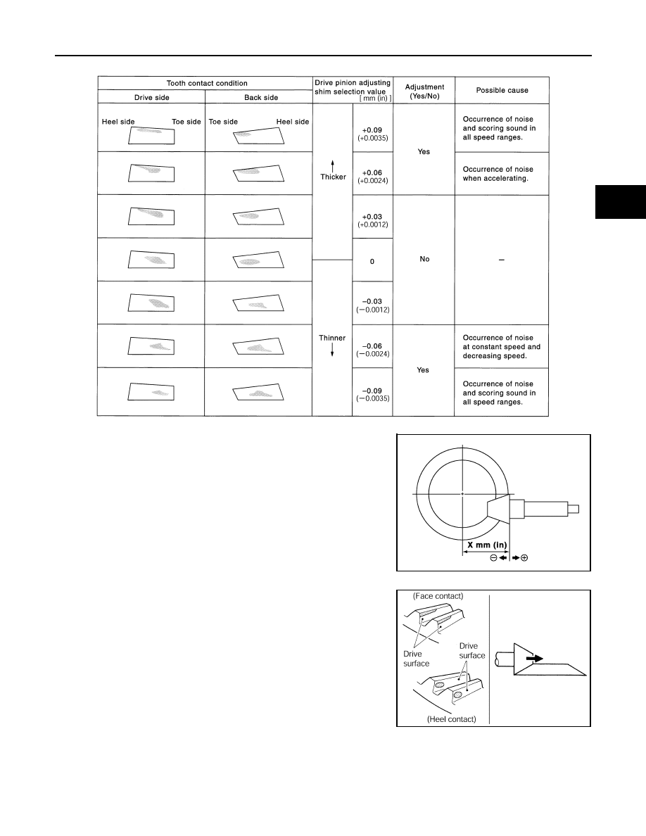
Tooth Contact Judgment Guide
5.
If tooth contact is improperly adjusted, follow the procedure
below to adjust the pinion height (dimension X).
• If the tooth contact is near the face (face contact), or near the
heel (heel contact), thicken drive pinion gear adjusting shim to
move drive pinion closer to drive gear.
SDIA2549E
SDIA0517E
PDIA0440E
DLN-124
< UNIT DISASSEMBLY AND ASSEMBLY >
[REAR FINAL DRIVE: R145]
DRIVE PINION
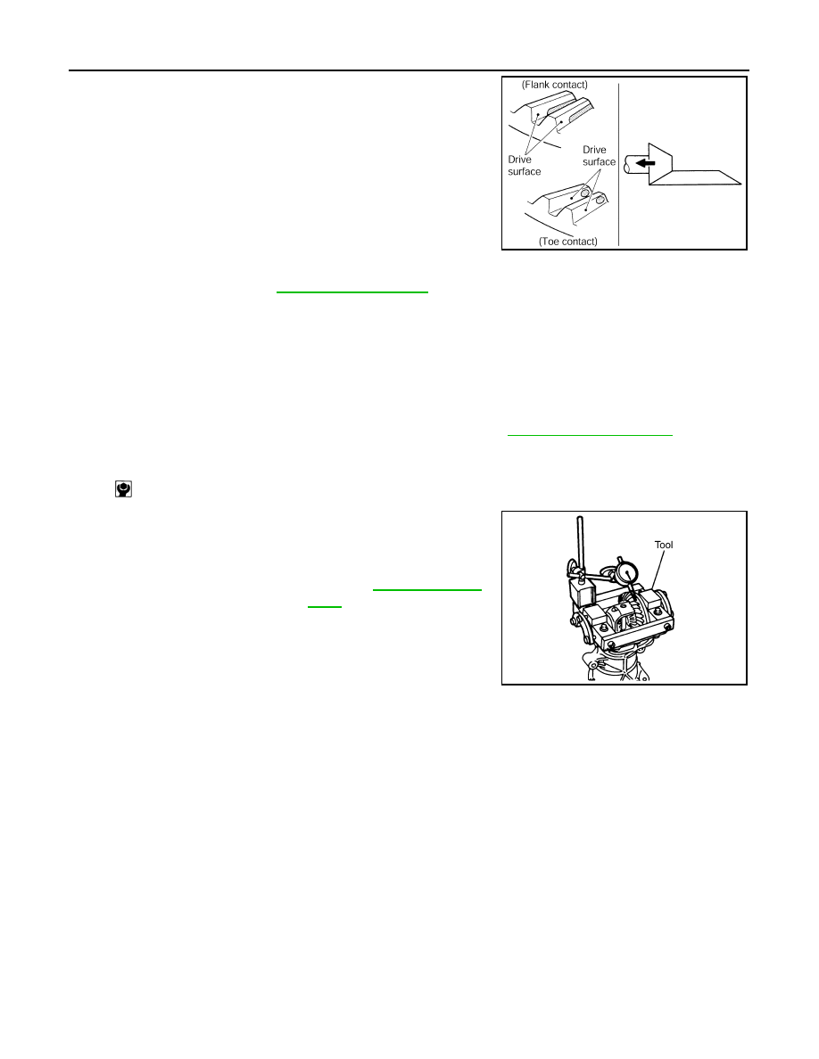
• If the tooth contact is near the flank (flank contact), or near the
toe (toe contact), thin drive pinion gear adjusting shim to move
drive pinion farther from drive gear.
BACKLASH
1.
Remove rear cover. Refer to
.
2.
Following the procedure below, install a dummy cover set [SST: KV381086S1 (
—
)] to gear car-
rier.
a.
Set dummy cover shims [SST: KV38108630 (
—
)] to the right and left side bearing adjusting
shims.
b.
Temporarily tighten dummy cover [SST: KV38108610 (
—
)] to gear carrier.
c.
Position dummy cover spacers [SST: KV38108621 (
—
)] to dummy cover [SST: KV38108610
(
—
)].
d.
Tighten rear cover mounting bolts to the specified torque. Refer to
.
e.
Tighten dummy cover spacer mounting bolts evenly to the specified torque.
3.
Fit a dial indicator to the drive gear face to measure the back-
lash.
• If the backlash is outside of the specified value, change the
thickness of side bearing adjusting shims.
Inspection After Disassembly
INFOID:0000000005514273
DRIVE GEAR AND DRIVE PINION
• Clean up the disassembled parts.
• If the gear teeth never mesh or line-up correctly, determine the cause and adjust or replace as necessary.
• If the gears are worn, cracked, damaged, pitted or chipped (by friction) noticeably, replace with new drive
gear and drive pinion as a set.
BEARING
• Clean up the disassembled parts.
• If any chipped (by friction), pitted, worn, rusted or scratched marks, or unusual noise from the bearing is
observed, replace as a bearing assembly (as a new set).
SIDE GEAR AND PINION MATE GEAR
PDIA0441E
: 5.9 N·m (0.6 kg-m, 52 in-lb)
Standard
Backlash
: Refer to
.
When the backlash is large:
Make drive gear back adjusting shims thicker, and drive
gear front adjusting shims thinner.
When the backlash is small:
Make drive gear back adjusting shims thinner, and
drive gear front adjusting shims thicker.
PDIA0049E
DRIVE PINION
DLN-125
< UNIT DISASSEMBLY AND ASSEMBLY >
[REAR FINAL DRIVE: R145]
C
E
F
G
H
I
J
K
L
M
A
B
DLN
N
O
P
• Clean up the disassembled parts.
• If any cracks or damage on the surface of the tooth is found, replace.
• If any worn or chipped mark on the contact sides of the thrust washer is found, replace.
SIDE GEAR THRUST WASHER AND PINION MATE THRUST WASHER
• Clean up the disassembled parts.
• If it is chipped (by friction), damaged, or unusually worn, replace.
OIL SEAL
• Whenever disassembled, replace.
• If wear, deterioration of adherence (sealing force lips), or damage is detected on the lips, replace them.
DIFFERENTIAL CASE
• Clean up the disassembled parts.
• If any wear or crack on the contact sides of the differential case is found, replace.
COMPANION FLANGE
• Clean up the disassembled parts.
• If any chipped mark [about 0.1 mm, (0.004 in)] or other damage on the contact sides of the lips of the com-
panion flange is found, replace.
Нет комментариевНе стесняйтесь поделиться с нами вашим ценным мнением.
Текст