Nissan Murano Z51. Instruction — part 610
EC-448
< DTC/CIRCUIT DIAGNOSIS >
[VQ35DE]
IGNITION SIGNAL
YES
>> GO TO 9.
NO
>> Repair open circuit, short to ground or short to power in harness or connectors.
9.
CHECK IGNITION COIL WITH POWER TRANSISTOR
EC-448, "Component Inspection (Ignition Coil with Power Transistor)"
.
Is the inspection result normal?
YES
>> GO TO 10.
NO
>> Replace malfunctioning ignition coil with power transistor.
10.
CHECK INTERMITTENT INCIDENT
GI-39, "Intermittent Incident"
>> INSPECTION END
Component Inspection (Ignition Coil with Power Transistor)
INFOID:0000000005536881
1.
CHECK IGNITION COIL WITH POWER TRANSISTOR-I
1.
Turn ignition switch OFF.
2.
Disconnect ignition coil harness connector.
3.
Check resistance between ignition coil terminals as per the following.
Is the inspection result normal?
YES
>> GO TO 2.
NO
>> Replace malfunctioning ignition coil with power transistor.
2.
CHECK IGNITION COIL WITH POWER TRANSISTOR-II
CAUTION:
Perform the following procedure in a place with no combustible objects and good ventilation.
1.
Turn ignition switch OFF.
2.
Reconnect all harness connectors disconnected.
3.
Remove fuel pump fuse in IPDM E/R to release fuel pressure.
NOTE:
Do not use CONSULT-III to release fuel pressure, or fuel pressure applies again during the following pro-
cedure.
4.
Start engine.
5.
After engine stalls, crank it 2 or 3 times to release all fuel pressure.
6.
Turn ignition switch OFF.
7.
Remove all ignition coil harness connectors to avoid the electrical discharge from the ignition coils.
8.
Remove ignition coil and spark plug of the cylinder to be checked.
9.
Crank engine for 5 seconds or more to remove combustion gas in the cylinder.
10. Connect spark plug and harness connector to ignition coil.
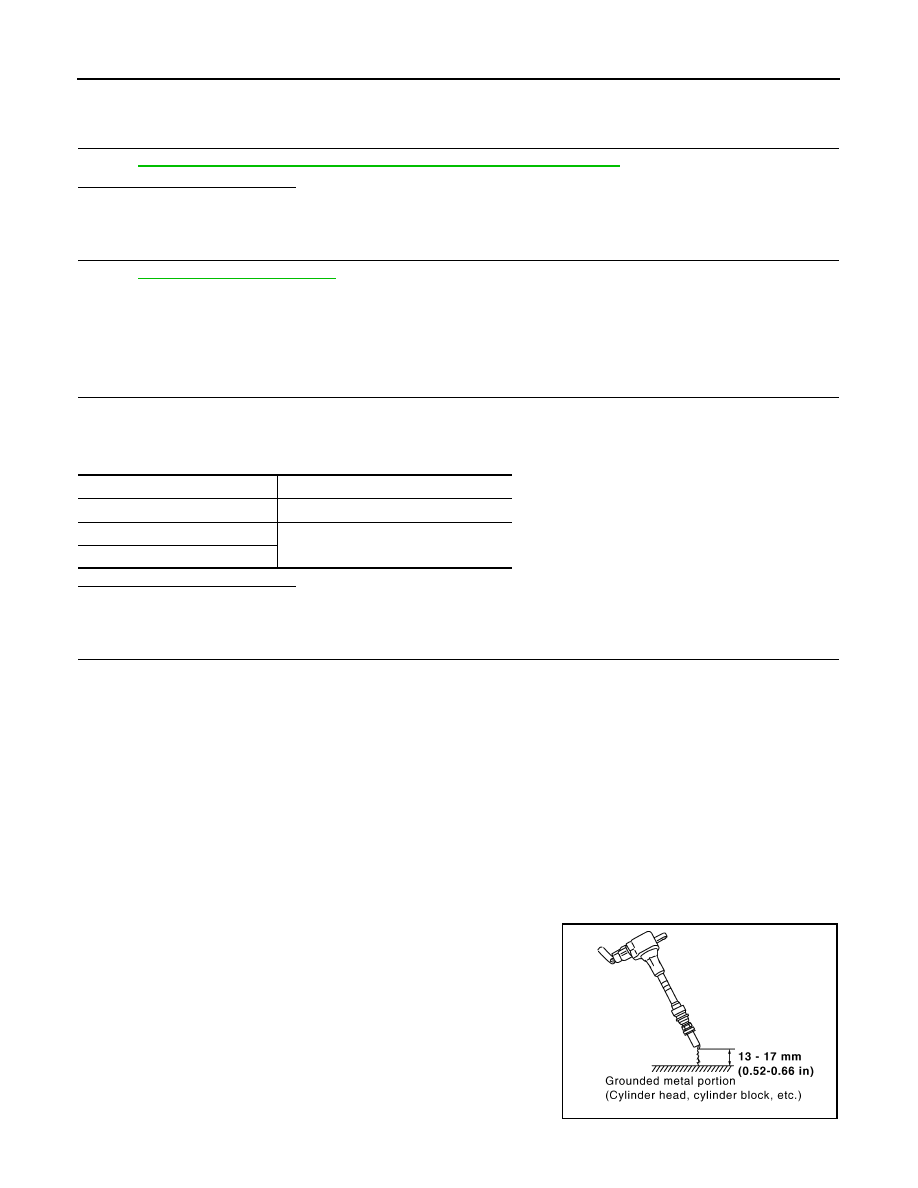
11. Fix ignition coil using a rope etc. with gap of 13 - 17 mm (0.52 -
0.66 in) between the edge of the spark plug and grounded metal
portion as shown in the figure.
12. Crank engine for approximately 3 seconds, and check whether
spark is generated between the spark plug and the grounded
metal portion.
CAUTION:
• During the operation, always stay 0.5 m (19.7 in) or more
away from the spark plug and the ignition coil. Be careful
Terminal No. (Polarity)
Resistance
Ω
[at 25
°
C (77
°
F)]
1 and 2
Except 0 or
∞
1 and 3
Except 0
2 and 3
Spark should be generated.
JMBIA0066GB
IGNITION SIGNAL
EC-449
< DTC/CIRCUIT DIAGNOSIS >
[VQ35DE]
C
D
E
F
G
H
I
J
K
L
M
A
EC
N
P
O
not to get an electrical shock while checking, because the electrical discharge voltage becomes
20 kV or more.
• It might cause to damage the ignition coil if the gap of more than 17 mm (0.66 in) is taken.
NOTE:
When the gap is less than 13 mm (0.52 in), the spark might be generated even if the coil is mal-
functioning.
Is the inspection result normal?
YES
>> INSPECTION END
NO
>> Replace malfunctioning ignition coil with power transistor.
Component Inspection (Condenser)
INFOID:0000000005536882
1.
CHECK CONDENSER
1.
Turn ignition switch OFF.
2.
Disconnect condenser harness connector.
3.
Check resistance between condenser terminals as per the following.
Is the inspection result normal?
YES
>> INSPECTION END
NO
>> Replace condenser.
Terminals
Resistance
1 and 2
Above 1 M
Ω
[at 25C
°
(77C
°
)]
EC-450
< DTC/CIRCUIT DIAGNOSIS >
[VQ35DE]
MALFUNCTION INDICATOR LAMP
MALFUNCTION INDICATOR LAMP
Description
INFOID:0000000005536883
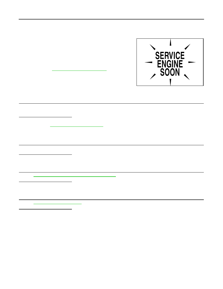
The Malfunction Indicator Lamp (MIL) is located on the combination
meter.
The MIL will illuminate when the ignition switch is turned ON without
the engine running. This is a bulb check.
When the engine is started, the MIL should turn off. If the MIL
remains on, the on board diagnostic system has detected an engine
system malfunction.
For details, refer to
EC-102, "Diagnosis Description"
.
Component Function Check
INFOID:0000000005536884
1.
CHECK MIL FUNCTION
1.
Turn ignition switch ON.
2.
Check that MIL illuminates.
Is the inspection result normal?
YES
>> INSPECTION END
NO
>> Go to
Diagnosis Procedure
INFOID:0000000005536885
1.
CHECK DTC
Check that DTC UXXXX is not displayed.
Is the inspection result normal?
YES
>> GO TO 2.
NO
>> Perform trouble diagnosis for DTC UXXXX.
2.
CHECK COMBINATION METER FUNCTION
MWI-34, "CONSULT-III Function (METER/M&A)"
.
Is the inspection result normal?
YES
>> GO TO 3.
NO
>> Repair or replace.
3.
CHECK INTERMITTENT INCIDENT
GI-39, "Intermittent Incident"
Is the inspection result normal?
YES
>> Replace combination meter.
NO
>> Repair or replace.
SEF217U
ON BOARD REFUELING VAPOR RECOVERY (ORVR)
EC-451
< DTC/CIRCUIT DIAGNOSIS >
[VQ35DE]
C
D
E
F
G
H
I
J
K
L
M
A
EC
N
P
O
ON BOARD REFUELING VAPOR RECOVERY (ORVR)
Description
INFOID:0000000005536886
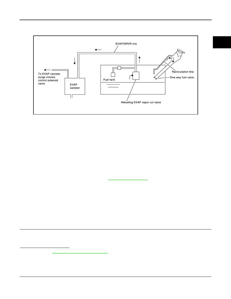
From the beginning of refueling, the air and vapor inside the fuel tank go through refueling EVAP vapor cut
valve and EVAP/ORVR line to the EVAP canister. The vapor is absorbed by the EVAP canister and the air is
released to the atmosphere.
When the refueling has reached the full level of the fuel tank, the refueling EVAP vapor cut valve is closed and
refueling is stopped because of auto shut-off. The vapor which was absorbed by the EVAP canister is purged
during driving.
WARNING:
When conducting inspections below, be sure to observe the following:
• Put a “CAUTION: FLAMMABLE” sign in workshop.
• Never smoke while servicing fuel system. Keep open flames and sparks away from work area.
• Always to furnish the workshop with a CO
2
fire extinguisher.
CAUTION:
• Before removing fuel line parts, carry out the following procedures:
- Put drained fuel in an explosion-proof container and put lid on securely.
- Release fuel pressure from fuel line. Refer to
- Disconnect battery ground cable.
• Always replace O-ring when the fuel gauge retainer is removed.
• Never kink or twist hose and tube when they are installed.
• Never tighten hose and clamps excessively to avoid damaging hoses.
• After installation, run engine and check for fuel leakage at connections.
• Never attempt to top off the fuel tank after the fuel pump nozzle shuts off automatically.
Continued refueling may cause fuel overflow, resulting in fuel spray and possibly a fire.
Component Function Check
INFOID:0000000005536887
1.
CHECK ORVR FUNCTION
Check whether the following symptoms are present.
• Fuel odor from EVAP canister is strong.
• Cannot refuel/Fuel odor from the fuel filler opening is strong while refueling.
Are any symptoms present?
YES
>> Go to
NO
>> INSPECTION END
Diagnosis Procedure
INFOID:0000000005536888
1.
INSPECTION START
Check whether the following symptoms are present.
A: Fuel odor from EVAP canister is strong.
PBIB1068E
Нет комментариевНе стесняйтесь поделиться с нами вашим ценным мнением.
Текст