Nissan Pathfinder (2012 year). Instruction — part 299
ENGINE CONTROL SYSTEM
EC-473
< WIRING DIAGRAM >
[VQ40DE]
C
D
E
F
G
H
I
J
K
L
M
A
EC
N
P
O
AABIA0743GB
August 2012
2012 Pathfinder
EC-474
< WIRING DIAGRAM >
[VQ40DE]
ENGINE CONTROL SYSTEM
ABBIA0433GB
August 2012
2012 Pathfinder

ENGINE CONTROL SYSTEM SYMPTOMS
EC-475
< SYMPTOM DIAGNOSIS >
[VQ40DE]
C
D
E
F
G
H
I
J
K
L
M
A
EC
N
P
O
SYMPTOM DIAGNOSIS
ENGINE CONTROL SYSTEM SYMPTOMS
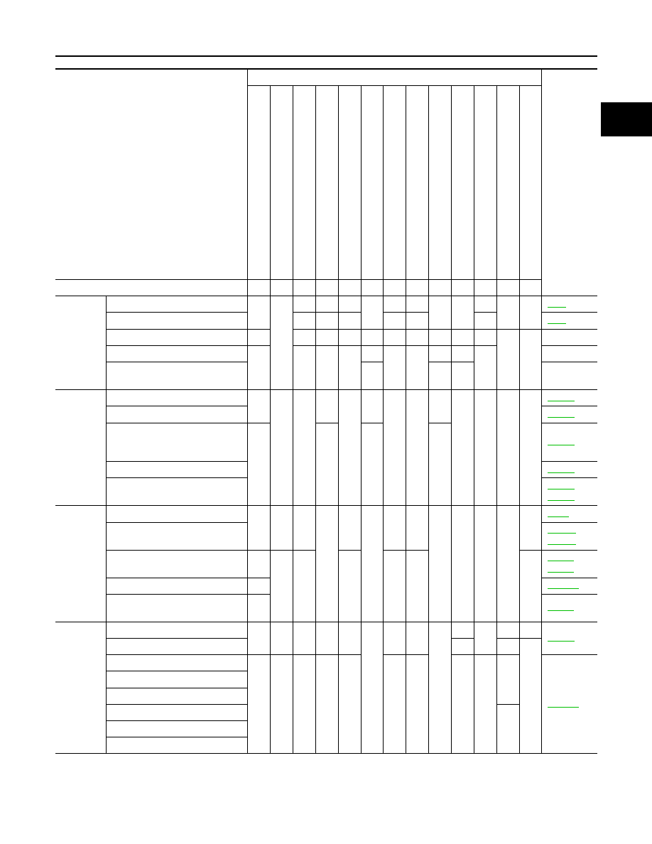
Symptom Matrix Chart
INFOID:0000000007358395
SYSTEM — BASIC ENGINE CONTROL SYSTEM
SYMPTOM
Reference
page
HARD/NO ST
AR
T
/REST
AR
T
(EXCP
.
H
A
)
ENGINE ST
ALL
HESIT
A
TION/SURGING/FLA
T
SPOT
SP
ARK KNOCK/DET
O
NA
TION
LACK
OF POWER/
POOR
ACC
E
LERA
TION
HIGH IDL
E/LOW
IDLE
ROUG
H IDLE/HUNTING
IDLI
NG VIBRA
TION
SLOW
/NO RETURN T
O
IDLE
OVERHEA
T
S/W
A
TER TEMPERA
T
UR
E
HIGH
EXCESS
IVE F
U
E
L CONSUMP
T
IO
N
EXCESS
IVE OIL CONSUMP
T
ION
BA
TTER
Y
DEAD (UNDER CHARGE)
Warranty symptom code
AA
AB
AC
AD
AE
AF AG AH
AJ
AK
AL
AM HA
Fuel
Fuel pump circuit
1
1
2
3
2
2
2
3
2
Fuel pressure regulator system
3
3
4
4
4
4
4
4
4
4
Fuel injector circuit
1
1
2
3
2
2
2
2
Evaporative emission system
3
3
4
4
4
4
4
4
4
4
Air
Positive crankcase ventilation sys-
tem
3
3
4
4
4
4
4
4
4
4
1
Incorrect idle speed adjustment
1
1
1
1
1
Electric throttle control actuator
1
1
2
3
3
2
2
2
2
2
2
,
Ignition Incorrect ignition timing adjustment
3
3
1
1
1
1
1
1
Ignition circuit
1
1
2
2
2
2
2
2
Power supply and ground circuit
2
2
3
3
3
3
3
2
3
Mass air flow sensor circuit
1
1
2
2
2
2
2
2
,
Engine coolant temperature sensor circuit
3
3
3
,
Air fuel ratio (A/F) sensor 1
EC-148
EC-152
EC-156
EC-160
EC-388
Throttle position sensor circuit
2
2
,
,
,
,
Accelerator pedal position sensor circuit
3
2
1
August 2012
2012 Pathfinder

EC-476
< SYMPTOM DIAGNOSIS >
[VQ40DE]
ENGINE CONTROL SYSTEM SYMPTOMS
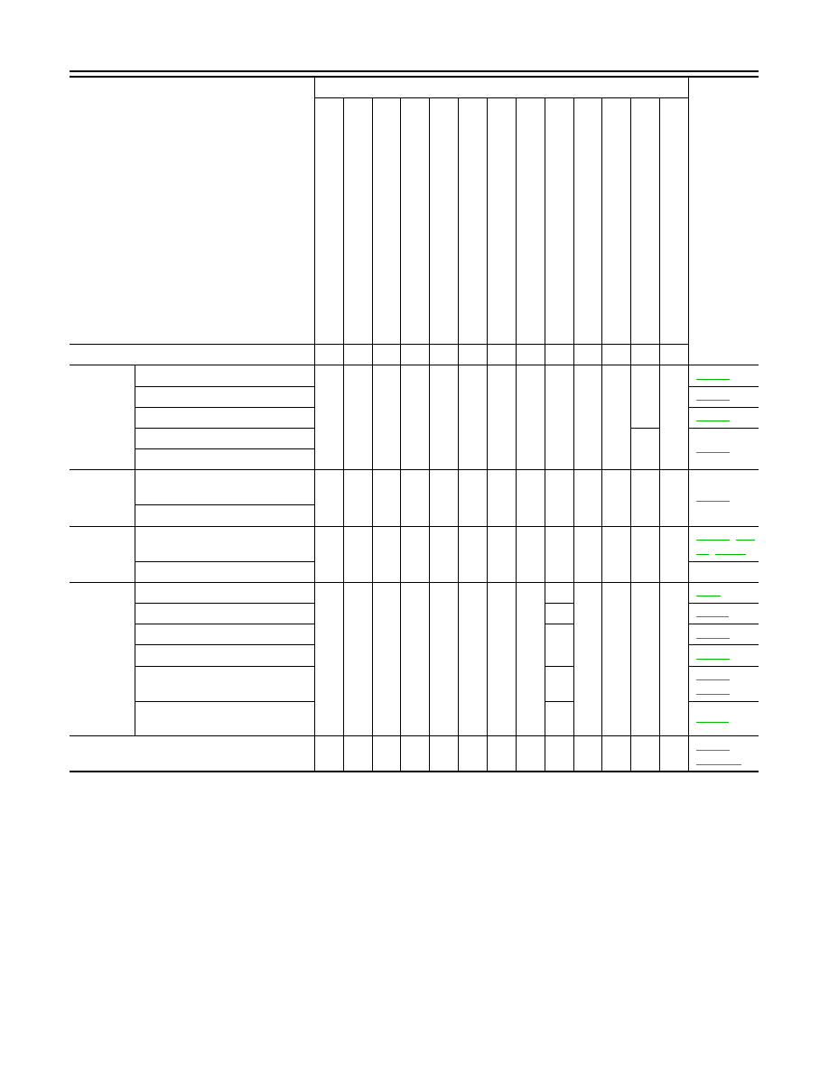
1 - 6: The numbers refer to the order of inspection.
(continued on next page)
SYSTEM — ENGINE MECHANICAL & OTHER
Knock sensor circuit
2
3
Crankshaft position sensor (POS) circuit
2
2
Camshaft position sensor (PHASE) circuit
3
2
Vehicle speed signal circuit
2
3
3
3
Power steering pressure sensor circuit
2
3
3
ECM
2
2
3
3
3
3
3
3
3
3
3
Intake valve timing control solenoid valve cir-
cuit
3
2
1
3
2
2
3
3
PNP signal circuit
3
3
3
3
3
VIAS control solenoid valve circuit
1
Refrigerant pressure sensor circuit
2
3
3
4
Electrical load signal circuit
3
Air conditioner circuit
2
2
3
3
3
3
3
3
3
3
2
,
ABS actuator and electric unit (control unit)
4
SYMPTOM
Reference
page
HARD/NO S
TA
R
T/RES
TA
R
T (E
XCP
. HA)
E
N
GINE
ST
ALL
HES
IT
A
TION/SURGING/FLA
T
SPOT
S
P
ARK KNOC
K
/DET
O
NA
TI
ON
LACK OF
POWER/POOR ACCELERA
TION
HIG
H
IDL
E
/L
OW
ID
LE
ROUGH IDLE/HUNTING
ID
LING VI
BRA
T
ION
S
LOW/NO RETU
RN
T
O ID
LE
OVERHEA
T
S
/W
A
TER TEMPERA
T
URE HIG
H
E
XCESSIVE
FUEL CON
S
UMP
T
ION
E
XCESSIVE
OIL
C
O
NSUMP
T
ION
B
A
TTER
Y
DEAD (UNDER CHARGE)
Warranty symptom code
AA
AB
AC AD
AE
AF AG AH
AJ
AK
AL
AM HA
August 2012
2012 Pathfinder
ENGINE CONTROL SYSTEM SYMPTOMS
EC-477
< SYMPTOM DIAGNOSIS >
[VQ40DE]
C
D
E
F
G
H
I
J
K
L
M
A
EC
N
P
O
SYMPTOM
Reference
page
HARD/NO ST
AR
T/REST
AR
T (EXCP
.
HA)
E
N
GI
N
E
ST
AL
L
HESIT
A
TION/S
U
R
GING/F
LA
T SP
OT
SP
ARK KNOCK/DE
T
O
NA
TION
LACK OF POWE
R/POOR
ACCELERA
TIO
N
HIGH IDL
E/L
OW
IDL
E
ROUG
H IDLE/HU
NTING
IDL
ING VIBRA
T
ION
SLO
W
/NO RETURN T
O
IDLE
OVERHEA
T
S/W
A
TE
R
TEMPERA
T
URE
HIGH
EXCES
SIVE F
U
EL CONSUMP
T
ION
EXCES
SIVE OI
L CONSUMP
T
IO
N
BA
TTE
R
Y
DEAD (UN
D
E
R
CH
A
R
GE)
Warranty symptom code
AA
AB
AC
AD
AE
AF
AG AH
AJ
AK
AL
AM HA
Fuel
Fuel tank
5
5
Fuel piping
5
5
5
5
5
5
Vapor lock
—
Valve deposit
5
5
5
5
5
5
5
—
Poor fuel (Heavy weight gasoline,
Low octane)
—
Air
Air duct
5
5
5
5
5
5
Air cleaner
Air leakage from air duct
(Mass air flow sensor — electric
throttle control actuator)
5
5
5
5
Electric throttle control actuator
Air leakage from intake manifold/
Collector/Gasket
Cranking
Battery
1
1
1
1
1
1
1
1
Generator circuit
Starter circuit
3
Signal plate
6
Park/neutral position (PNP) sig-
nal
4
Engine
Cylinder head
5
5
5
5
5
5
5
5
Cylinder head gasket
4
3
Cylinder block
6
6
6
6
6
6
6
6
4
Piston
Piston ring
Connecting rod
Bearing
Crankshaft
August 2012
2012 Pathfinder
EC-478
< SYMPTOM DIAGNOSIS >
[VQ40DE]
ENGINE CONTROL SYSTEM SYMPTOMS
1 - 6: The numbers refer to the order of inspection.
Valve
mecha-
nism
Timing chain
5
5
5
5
5
5
5
5
Camshaft
Intake valve timing control
Intake valve
3
Exhaust valve
Exhaust
Exhaust manifold/Tube/Muffler/
Gasket
5
5
5
5
5
5
5
5
,
Three way catalyst
Lubrica-
tion
Oil pan/Oil strainer/Oil pump/Oil
filter/Oil gallery/Oil cooler
5
5
5
5
5
5
5
5
Oil level (Low)/Filthy oil
Cooling
Radiator/Hose/Radiator filler cap
5
5
5
5
5
5
5
4
5
Thermostat
5
Water pump
Water gallery
Cooling fan
5
or
Coolant level (Low)/Contaminat-
ed coolant
5
NVIS (NISSAN Vehicle Immobilizer System —
NATS)
1
1
or
SYMPTOM
Reference
page
HARD/NO S
TA
R
T/RES
TA
R
T (E
XCP
. HA)
E
N
GINE
ST
ALL
HES
IT
A
TION/SURGING/FLA
T
SPOT
S
P
ARK KNOC
K
/DET
O
NA
TI
ON
LACK OF
POWER/POOR ACCELERA
TION
HIG
H
IDL
E
/L
OW
ID
LE
ROUGH IDLE/HUNTING
ID
LING VI
BRA
T
ION
S
LOW/NO RETU
RN
T
O ID
LE
OVERHEA
T
S
/W
A
TER TEMPERA
T
URE HIG
H
E
XCESSIVE
FUEL CON
S
UMP
T
ION
E
XCESSIVE
OIL
C
O
NSUMP
T
ION
B
A
TTER
Y
DEAD (UNDER CHARGE)
Warranty symptom code
AA
AB
AC
AD
AE
AF
AG AH
AJ
AK
AL
AM HA
August 2012
2012 Pathfinder
NORMAL OPERATING CONDITION
EC-479
< SYMPTOM DIAGNOSIS >
[VQ40DE]
C
D
E
F
G
H
I
J
K
L
M
A
EC
N
P
O
NORMAL OPERATING CONDITION
Fuel Cut Control (at No Load and High Engine Speed)
INFOID:0000000007358396
INPUT/OUTPUT SIGNAL CHART
*: This signal is sent to the ECM through CAN communication line.
SYSTEM DESCRIPTION
If the engine speed is above 1,800 rpm under no load (for example, the shift position is neutral and engine
speed is over 1,800 rpm) fuel will be cut off after some time. The exact time when the fuel is cut off varies
based on engine speed.
Fuel cut will be operated until the engine speed reaches 1,500 rpm, then fuel cut will be cancelled.
NOTE:
This function is different from deceleration control listed under
.
Sensor
Input Signal to ECM
ECM function
Actuator
TCM
Neutral position
Fuel cut control Fuel injector
Accelerator pedal position sensor
Accelerator pedal position
Engine coolant temperature sensor
Engine coolant temperature
Crankshaft position sensor (POS)
Camshaft position sensor (PHASE)
Engine speed
Wheel sensor
Vehicle speed*
August 2012
2012 Pathfinder
EC-480
< PRECAUTION >
[VQ40DE]
PRECAUTIONS
PRECAUTION
PRECAUTIONS
Precaution for Supplemental Restraint System (SRS) "AIR BAG" and "SEAT BELT
PRE-TENSIONER"
INFOID:0000000008832066
The Supplemental Restraint System such as “AIR BAG” and “SEAT BELT PRE-TENSIONER”, used along
with a front seat belt, helps to reduce the risk or severity of injury to the driver and front passenger for certain
types of collision. This system includes seat belt switch inputs and dual stage front air bag modules. The SRS
system uses the seat belt switches to determine the front air bag deployment, and may only deploy one front
air bag, depending on the severity of a collision and whether the front occupants are belted or unbelted.
Information necessary to service the system safely is included in the SR and SB section of this Service Man-
ual.
WARNING:
• To avoid rendering the SRS inoperative, which could increase the risk of personal injury or death in
the event of a collision which would result in air bag inflation, all maintenance must be performed by
an authorized NISSAN/INFINITI dealer.
• Improper maintenance, including incorrect removal and installation of the SRS, can lead to personal
injury caused by unintentional activation of the system. For removal of Spiral Cable and Air Bag
Module, see the SR section.
• Do not use electrical test equipment on any circuit related to the SRS unless instructed to in this
Service Manual. SRS wiring harnesses can be identified by yellow and/or orange harnesses or har-
ness connectors.
PRECAUTIONS WHEN USING POWER TOOLS (AIR OR ELECTRIC) AND HAMMERS
WARNING:
• When working near the Airbag Diagnosis Sensor Unit or other Airbag System sensors with the Igni-
tion ON or engine running, DO NOT use air or electric power tools or strike near the sensor(s) with a
hammer. Heavy vibration could activate the sensor(s) and deploy the air bag(s), possibly causing
serious injury.
• When using air or electric power tools or hammers, always switch the Ignition OFF, disconnect the
battery and wait at least 3 minutes before performing any service.
Precaution Necessary for Steering Wheel Rotation After Battery Disconnect
INFOID:0000000007833552
NOTE:
• This Procedure is applied only to models with Intelligent Key system and NATS (NISSAN ANTI-THEFT SYS-
TEM).
• Remove and install all control units after disconnecting both battery cables with the ignition knob in the
″
LOCK
″
position.
• Always use CONSULT to perform self-diagnosis as a part of each function inspection after finishing work. If
DTC is detected, perform trouble diagnosis according to self-diagnostic results.
For models equipped with the Intelligent Key system and NATS, an electrically controlled steering lock mech-
anism is adopted on the key cylinder.
For this reason, if the battery is disconnected or if the battery is discharged, the steering wheel will lock and
steering wheel rotation will become impossible.
If steering wheel rotation is required when battery power is interrupted, follow the procedure below before
starting the repair operation.
OPERATION PROCEDURE
1. Connect both battery cables.
NOTE:
Supply power using jumper cables if battery is discharged.
2. Use the Intelligent Key or mechanical key to turn the ignition switch to the
″
ACC
″
position. At this time, the
steering lock will be released.
3. Disconnect both battery cables. The steering lock will remain released and the steering wheel can be
rotated.
4. Perform the necessary repair operation.
August 2012
2012 Pathfinder
Нет комментариевНе стесняйтесь поделиться с нами вашим ценным мнением.
Текст