Nissan Pathfinder (2012 year). Instruction — part 255
P0102, P0103 MAF SENSOR
EC-121
< DTC/CIRCUIT DIAGNOSIS >
[VQ40DE]
C
D
E
F
G
H
I
J
K
L
M
A
EC
N
P
O
With CONSULT
1. Reconnect all harness connectors disconnected.
2. Start engine and warm it up to normal operating temperature.
3. Connect CONSULT and select “DATA MONITOR” mode.
4. Select “MAS A/F SE-B1” and check indication under the following conditions.
*: Check for linear voltage rise in response to engine being increased to about 4,000 rpm.
5. If the voltage is out of specification, proceed the following.
a. Check for the cause of uneven air flow through mass air flow sensor. Refer to following.
• Crushed air ducts
• Malfunctioning seal of air cleaner element
• Uneven dirt of air cleaner element
• Improper specification of intake air system parts
b. If NG, repair or replace malfunctioning part and perform step 2 to 4 again.
If OK, go to next step.
6. Turn ignition switch OFF.
7. Disconnect mass air flow sensor harness connector and reconnect it again.
8. Perform step 2 to 4 again.
9. If NG, clean or replace mass air flow sensor. Refer to
EM-26, "Removal and Installation"
Without CONSULT
1. Reconnect all harness connectors disconnected.
2. Start engine and warm it up to normal operating temperature.
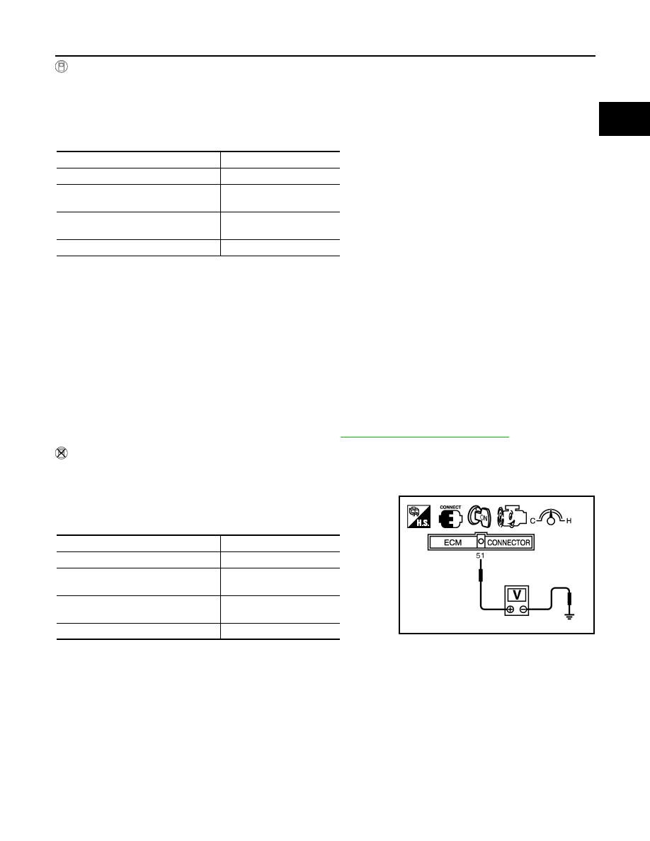
3. Check voltage between ECM terminal 51 (Mass air flow sensor
signal) and ground.
*: Check for linear voltage rise in response to engine being increased to about 4,000 rpm.
4. If the voltage is out of specification, proceed the following.
a. Check for the cause of uneven air flow through mass air flow sensor. Refer to following.
• Crushed air ducts
• Malfunctioning seal of air cleaner element
• Uneven dirt of air cleaner element
• Improper specification of intake air system parts
b. If NG, repair or replace malfunctioning part and perform step 2 to 3 again.
If OK, go to next step.
5. Turn ignition switch OFF.
6. Disconnect mass air flow sensor harness connector and reconnect it again.
7. Perform step 2 and 3 again.
Condition
MAS A/F SE-B1 (V)
Ignition switch ON (Engine stopped.)
Approx. 0.4
Idle (Engine is warmed-up to normal
operating temperature.)
0.9 - 1.2
2,500 rpm (Engine is warmed-up to
normal operating temperature.)
1.5 - 1.8
Idle to about 4,000 rpm
0.9 - 1.2 to Approx. 2.4*
Condition
Voltage V
Ignition switch ON (Engine stopped.)
Approx. 0.4
Idle (Engine is warmed-up to normal
operating temperature.)
0.9 - 1.2
2,500 rpm (Engine is warmed-up to
normal operating temperature.)
1.5 - 1.8
Idle to about 4,000 rpm
0.9 - 1.2 to Approx. 2.4*
PBIB1106E
August 2012
2012 Pathfinder
EC-122
< DTC/CIRCUIT DIAGNOSIS >
[VQ40DE]
P0102, P0103 MAF SENSOR
8. If NG, clean or replace mass air flow sensor. Refer to
EM-26, "Removal and Installation"
August 2012
2012 Pathfinder
P0111 IAT SENSOR
EC-123
< DTC/CIRCUIT DIAGNOSIS >
[VQ40DE]
C
D
E
F
G
H
I
J
K
L
M
A
EC
N
P
O
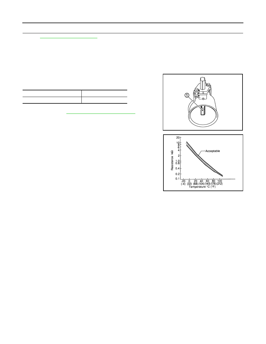
P0111 IAT SENSOR
Component Description
INFOID:0000000007358025
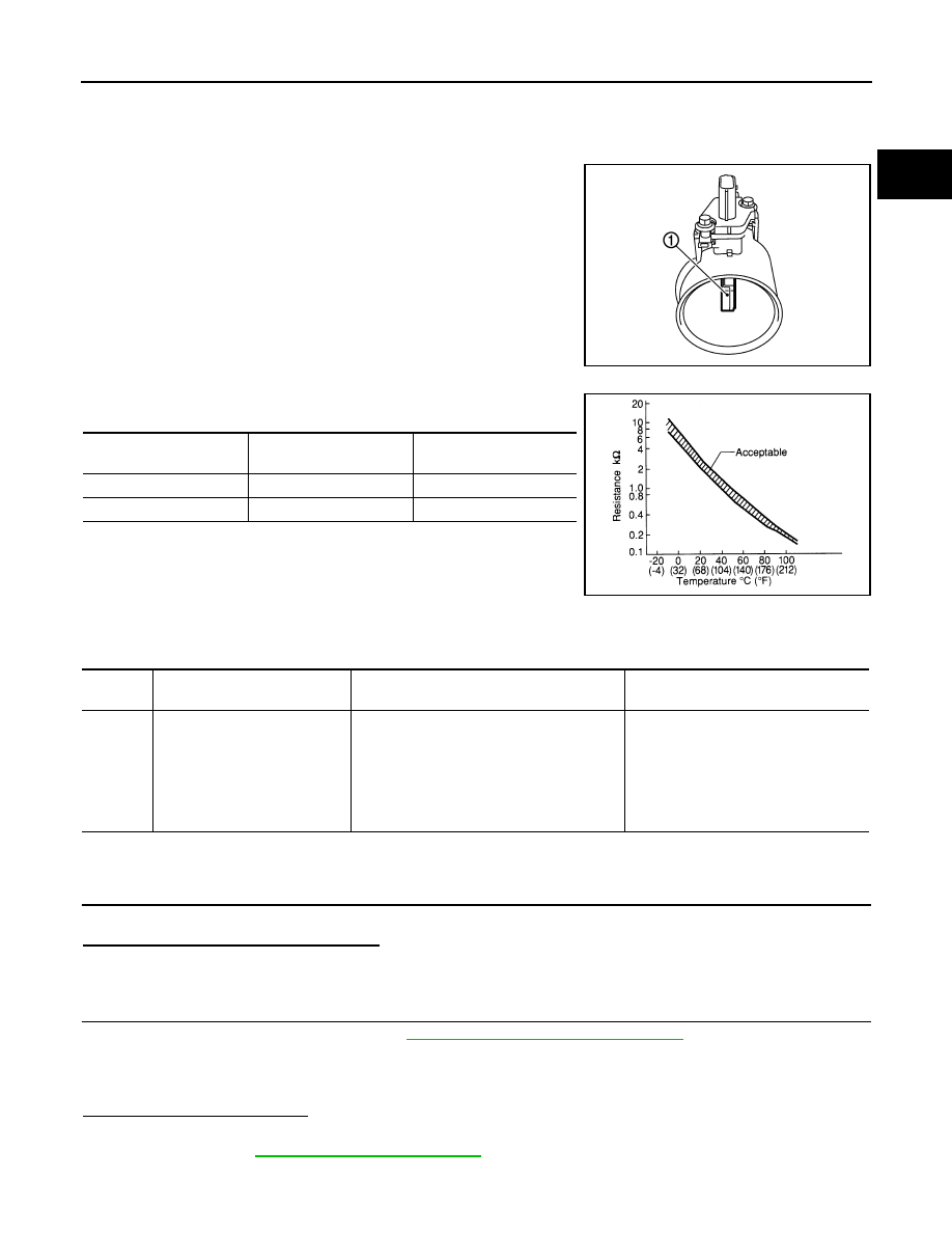
The intake air temperature sensor is built-into the mass air flow sen-
sor (1). The sensor detects intake air temperature and transmits a
signal to the ECM.
The temperature sensing unit uses a thermistor which is sensitive to
the change in temperature. Electrical resistance of the thermistor
decreases in response to the rise in temperature.
<Reference data>
*: These data are reference values and are measured between ECM terminals 51
(Intake air temperature sensor) and 67 (Sensor ground).
On Board Diagnosis Logic
INFOID:0000000007358026
DTC Confirmation Procedure
INFOID:0000000007358027
1.
INSPECTION START
Is it necessary to erase permanent DTC?
YES
>> GO TO 3.
NO
>> GO TO 2.
2.
PERFORM COMPONENT FUNCTION CHECK
Perform component function check. Refer to
EC-124, "Component Function Check"
.
NOTE:
Use the component function check to check the overall function of the IAT sensor circut. During this check, a
1st trip DTC might not be confirmed.
Is the inspection result normal?
YES
>> INSPECTION END
NO
>> Proceed to
.
PBIA9559J
Intake air temperature
[
°
C (
°
F)]
Voltage* (V)
Resistance (k
Ω
)
25 (77)
3.3
1.800 - 2.200
80 (176)
1.2
0.283 - 0.359
SEF012P
DTC No.
Trouble diagnosis
(Trouble diagnosis content)
DTC detecting condition
Possible cause
P0111
IAT SENSOR 1 B1
[Intake air temperature (IAT)
sensor circuit range/perfor-
mance]
The comparison result of signals transmitted
to ECM from each temperature sensor (IAT
sensor, ECT sensor, and FTT sensor) shows
that the voltage signal of the IAT sensor is
higher/lower than that of other temperature
sensors when the engine is started with its
cold state.
• Harness or connectors
(High or low resistance in the IAT sen-
sor circuit)
• IAT sensor
August 2012
2012 Pathfinder

EC-124
< DTC/CIRCUIT DIAGNOSIS >
[VQ40DE]
P0111 IAT SENSOR
3.
PRECONDITIONING
If DTC CONFIRMATION PROCEDURE has been previously conducted, always perform the following proce-
dure before conducting the next test.
1. Turn ignition switch OFF and wait at least 10 seconds.
2. Turn ignition switch ON.
3. Turn ignition switch OFF and wait at least 10 seconds.
TESTING CONDITION:
•
Before performing the following procedure, do not add fuel.
•
Before performing the following procedure, check that fuel level is between 1/4 and 4/4.
•
Before performing the following procedure, confirm that battery voltage is 11 V or more at idle.
>> GO TO 4.
4.
PERFORM DTC CONFIRMATION PROCEDURE
1. Start engine and let it idle for 60 minutes.
2. Move the vehicle to a cool place.
NOTE:
Cool the vehicle in an environment of ambient air temperature between
−
10
°
C (14
°
F) and 35
°
C (95
°
F).
3. Turn ignition switch OFF and soak the vehicle for 12 hours.
CAUTION:
Never turn ignition switch ON during soaking.
NOTE:
The vehicle must be cooled with the food open.
4. Start engine and let it idle for 5 minutes or more.
CAUTION:
Never turn ignition switch OFF during idling.
5. Check 1st trip DTC.
Is 1st trip DTC detected?
YES
>> Proceed to
.
NO
>> INSPECTION END
Component Function Check
INFOID:0000000007358028
1.
CHECK INTAKE AIR TEMPERATURE (IAT) SENSOR
1. Turn ignition switch OFF.
2. Disconnect mass air flow sensor harness connector.
3. Check resistance between mass air flow sensor terminals as follows.
Is the inspection result normal?
YES
>> GO TO 2.
NO
>> Proceed to
.
2.
CHECK INTERMITTENT INCIDENT
Check intermittent incident. Refer to
GI-37, "Intermittent Incident"
.
Is the inspection result normal?
YES
>> INSPECTION END
NO
>> Proceed to
.
Diagnosis Procedure
INFOID:0000000007358029
1.
CHECK INTAKE AIR TEMPERATURE (IAT) SENSOR
Check intake air temperature sensor. Refer to
EC-125, "Component Inspection"
.
Is the inspection result normal?
YES
>> GO TO 2.
Terminals
Condition
Resistance (k
Ω
)
5 and 6
Temperature [
°
C (
°
F)]
25 (77)
1.800 – 2.200
August 2012
2012 Pathfinder

P0111 IAT SENSOR
EC-125
< DTC/CIRCUIT DIAGNOSIS >
[VQ40DE]
C
D
E
F
G
H
I
J
K
L
M
A
EC
N
P
O
NO
>> Replace mass air flow sensor (with intake air temperature sensor). Refer to
2.
CHECK INTERMITTENT INCIDENT
Check intermittent incident. Refer to
GI-37, "Intermittent Incident"
.
>> INSPECTION END
Component Inspection
INFOID:0000000007358030
1.
CHECK INTAKE AIR TEMPERATURE (IAT) SENSOR
1. Turn ignition switch OFF.
2. Disconnect mass air flow sensor harness connector.
3. Check resistance between mass air flow sensor terminals as follows.
Is the inspection result normal?
YES
>> INSPECTION END
NO
>> Replace mass air flow sensor (with intake air temperature sensor). Refer to
Terminals
Condition
Resistance (k
Ω
)
5 and 6
Temperature [
°
C (
°
F)]
25 (77)
1.800 – 2.200
August 2012
2012 Pathfinder
EC-126
< DTC/CIRCUIT DIAGNOSIS >
[VQ40DE]
P0112, P0113 IAT SENSOR
P0112, P0113 IAT SENSOR
Component Description
INFOID:0000000007358031
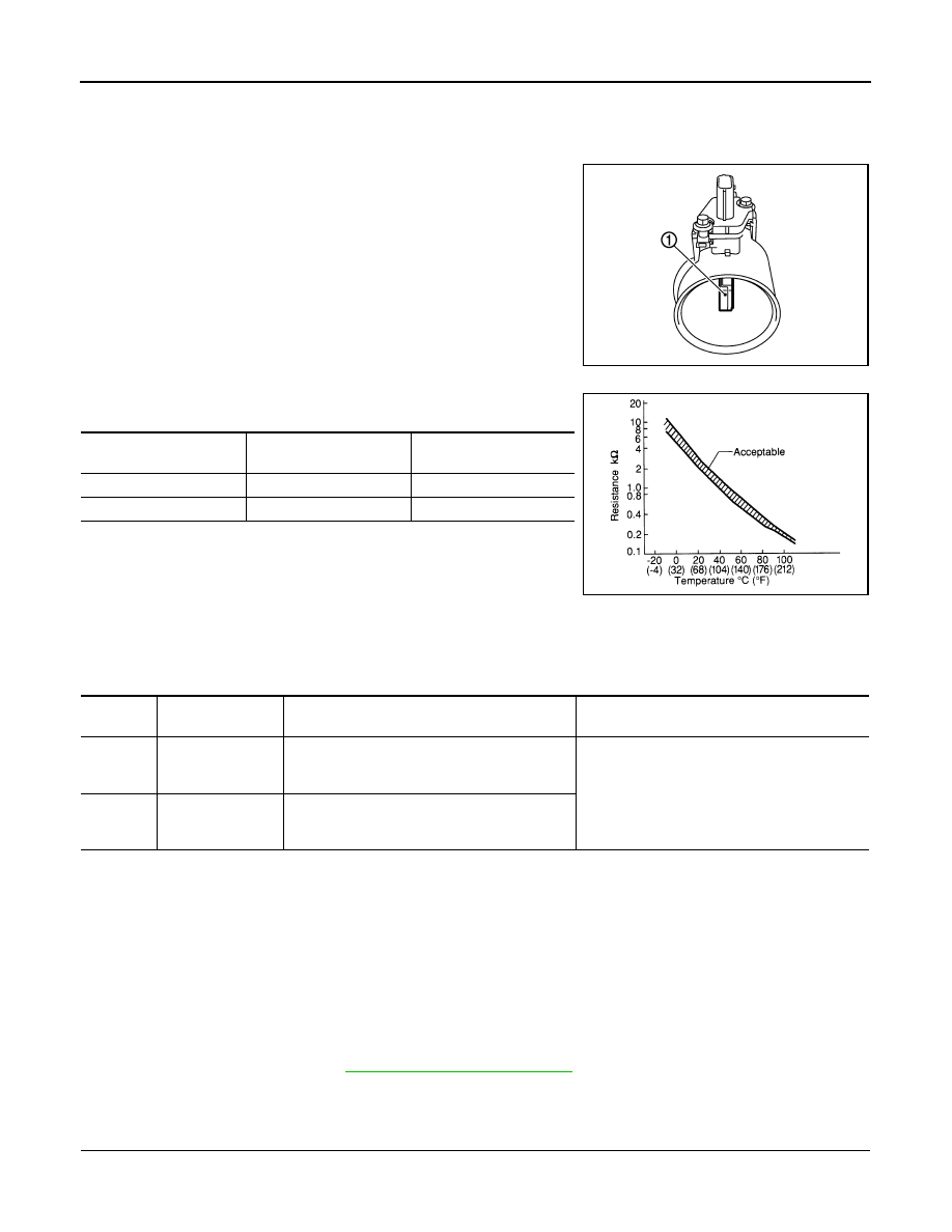
The intake air temperature sensor is built-into the mass air flow sen-
sor (1). The sensor detects intake air temperature and transmits a
signal to the ECM.
The temperature sensing unit uses a thermistor which is sensitive to
the change in temperature. Electrical resistance of the thermistor
decreases in response to the rise in temperature.
<Reference data>
*: This data is reference value and is measured between ECM terminal 34 (Intake air
temperature sensor) and ground.
CAUTION:
Never use ECM ground terminals when measuring input/output
voltage. Doing so may result in damage to the ECM's transistor.
Use a ground other than ECM terminals, such as the ground.
On Board Diagnosis Logic
INFOID:0000000007358032
DTC Confirmation Procedure
INFOID:0000000007358033
1. If DTC Confirmation Procedure has been previously conducted, always perform the following before con-
ducting the next step.
a. Turn ignition switch OFF and wait at least 10 seconds.
b. Turn ignition switch ON.
c.
Turn ignition switch OFF and wait at least 10 seconds.
2. Turn ignition switch ON and wait at least 5 seconds.
3. Check 1st trip DTC.
4. If 1st trip DTC is detected, go to
Diagnosis Procedure
INFOID:0000000007358034
1.
CHECK GROUND CONNECTIONS
1. Turn ignition switch OFF.
PBIA9559J
Intake air temperature
°
C (
°
F)
Voltage* V
Resistance k
Ω
25 (77)
3.3
1.800 - 2.200
80 (176)
1.2
0.283 - 0.359
SEF012P
DTC No.
Trouble diagnosis
name
DTC detecting condition
Possible cause
P0112
0112
Intake air tempera-
ture sensor circuit
low input
An excessively low voltage from the sensor is
sent to ECM.
• Harness or connectors
(The sensor circuit is open or shorted.)
• Intake air temperature sensor
P0113
0113
Intake air tempera-
ture sensor circuit
high input
An excessively high voltage from the sensor is
sent to ECM.
August 2012
2012 Pathfinder
P0112, P0113 IAT SENSOR
EC-127
< DTC/CIRCUIT DIAGNOSIS >
[VQ40DE]
C
D
E
F
G
H
I
J
K
L
M
A
EC
N
P
O
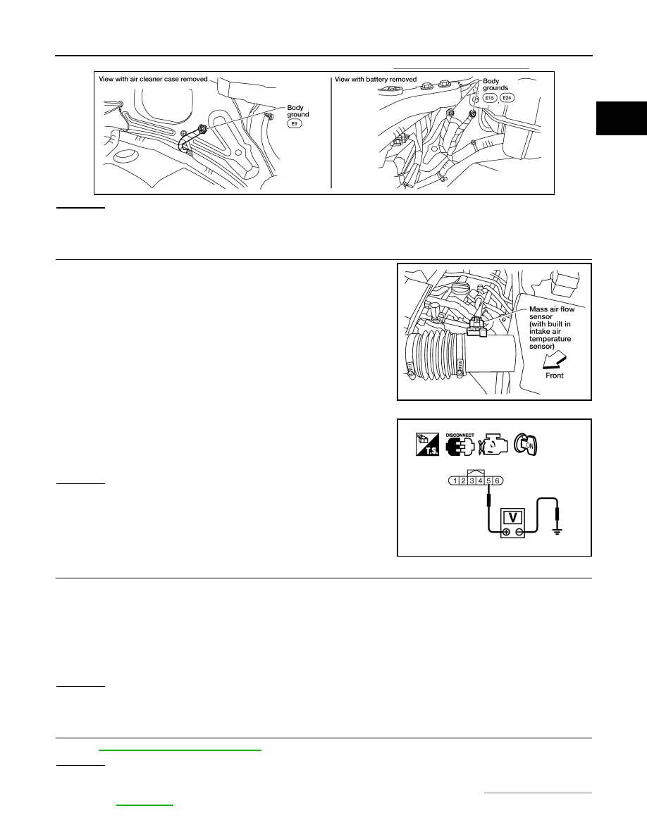
2. Loosen and retighten three ground screws on the body. Refer to
OK or NG
OK
>> GO TO 2.
NG
>> Repair or replace ground connections.
2.
CHECK INTAKE AIR TEMPERATURE SENSOR POWER SUPPLY CIRCUIT
1. Disconnect mass air flow sensor (intake air temperature sensor
is built-in) harness connector.
2. Turn ignition switch ON.
3. Check voltage between mass air flow sensor terminal 5 and
ground.
OK or NG
OK
>> GO TO 3.
NG
>> Repair harness or connectors.
3.
CHECK INTAKE AIR TEMPERATURE SENSOR GROUND CIRCUIT FOR OPEN AND SHORT
1. Turn ignition switch OFF.
2. Disconnect ECM harness connector.
3. Check harness continuity between mass air flow sensor terminal 6 and ECM terminal 67.
Refer to Wiring Diagram.
4. Also check harness for short to ground and short to power.
OK or NG
OK
>> GO TO 4.
NG
>> Repair open circuit or short to ground or short to power in harness or connectors.
4.
CHECK INTAKE AIR TEMPERATURE SENSOR
EC-128, "Component Inspection"
OK or NG
OK
>> GO TO 5.
NG
>> Replace mass air flow sensor (with intake air temperature sensor). Refer to
BBIA0539E
BBIA0541E
Voltage: Approximately 5V
PBIB1169E
Continuity should exist.
August 2012
2012 Pathfinder
EC-128
< DTC/CIRCUIT DIAGNOSIS >
[VQ40DE]
P0112, P0113 IAT SENSOR
5.
CHECK INTERMITTENT INCIDENT
GI-37, "Intermittent Incident"
>>
INSPECTION END
Component Inspection
INFOID:0000000007358035
INTAKE AIR TEMPERATURE SENSOR
1. Check resistance between mass air flow sensor (1) terminals 5
and 6 under the following conditions.
2. If NG, replace mass air flow sensor (with intake air temperature
sensor). Refer to
EM-26, "Removal and Installation"
.
Intake air temperature
°
C (
°
F)
Resistance k
Ω
25 (77)
1.800 - 2.200
PBIA9559J
SEF012P
August 2012
2012 Pathfinder
Нет комментариевНе стесняйтесь поделиться с нами вашим ценным мнением.
Текст