Nissan Pathfinder (2012 year). Instruction — part 506
PWC-78
< SYMPTOM DIAGNOSIS >
POWER WINDOW RETAINED POWER OPERATION DOES NOT OPERATE
PROPERLY
POWER WINDOW RETAINED POWER OPERATION DOES NOT OPER-
ATE PROPERLY
Diagnosis Procedure
INFOID:0000000007355924
1.
CHECK FRONT DOOR SWITCH
Check front door switch.
PWC-35, "Component Function Check"
.
Is the inspection result normal?
YES
>> Replace BCM. Refer to
BCS-53, "Removal and Installation"
NO
>> Check intermittent incident. Refer to
GI-37, "Intermittent Incident"
.
August 2012
2012 Pathfinder
DOES NOT OPERATE BY KEY CYLINDER SWITCH
PWC-79
< SYMPTOM DIAGNOSIS >
C
D
E
F
G
H
I
J
L
M
A
B
PWC
N
O
P
DOES NOT OPERATE BY KEY CYLINDER SWITCH
Diagnosis Procedure
INFOID:0000000007355925
1.
CHECK FRONT DOOR LOCK ASSEMBLY LH (KEY CYLINDER SWITCH)
Check front door lock assembly LH (key cylinder switch).
PWC-37, "Component Function Check"
.
Is the inspection result normal?
YES
>> Inspection End.
NO
>> Check intermittent incident. Refer to
GI-37, "Intermittent Incident"
.
August 2012
2012 Pathfinder

PWC-80
< SYMPTOM DIAGNOSIS >
KEYLESS POWER WINDOW DOWN DOES NOT OPERATE
KEYLESS POWER WINDOW DOWN DOES NOT OPERATE
Diagnosis Procedure
INFOID:0000000007355926
1.
CHECK INTELLIGENT KEY OR KEYFOB FUNCTION
Check Intelligent Key or keyfob function.
Refer to
BCS-23, "INTELLIGENT KEY : CONSULT Function (BCM - INTELLIGENT KEY)"
with Intelligent Key
or
BCS-19, "MULTI REMOTE ENT : CONSULT Function (BCM - MULTI REMOTE ENT)"
with remote keyless
entry system.
Is the inspection result normal?
YES
>> Check intermittent incident. Refer to
GI-37, "Intermittent Incident"
.
NO
>> Replace BCM. Refer to
BCS-53, "Removal and Installation"
August 2012
2012 Pathfinder
POWER WINDOW LOCK SWITCH DOES NOT FUNCTION
PWC-81
< SYMPTOM DIAGNOSIS >
C
D
E
F
G
H
I
J
L
M
A
B
PWC
N
O
P
POWER WINDOW LOCK SWITCH DOES NOT FUNCTION
Diagnosis Procedure
INFOID:0000000007355927
1.
REPLACE MAIN POWER WINDOW AND DOOR LOCK/UNLOCK SWITCH
Replace main power window and door lock/unlock switch.
PWC-85, "Removal and Installation"
.
Is the inspection result normal?
YES
>> Inspection End.
NO
>> Check intermittent incident. Refer to
GI-37, "Intermittent Incident"
.
August 2012
2012 Pathfinder
PWC-82
< PRECAUTION >
PRECAUTIONS
PRECAUTION
PRECAUTIONS
Precaution for Supplemental Restraint System (SRS) "AIR BAG" and "SEAT BELT
PRE-TENSIONER"
INFOID:0000000007355928
The Supplemental Restraint System such as “AIR BAG” and “SEAT BELT PRE-TENSIONER”, used along
with a front seat belt, helps to reduce the risk or severity of injury to the driver and front passenger for certain
types of collision. This system includes seat belt switch inputs and dual stage front air bag modules. The SRS
system uses the seat belt switches to determine the front air bag deployment, and may only deploy one front
air bag, depending on the severity of a collision and whether the front occupants are belted or unbelted.
Information necessary to service the system safely is included in the SR and SB section of this Service Man-
ual.
WARNING:
• To avoid rendering the SRS inoperative, which could increase the risk of personal injury or death in
the event of a collision which would result in air bag inflation, all maintenance must be performed by
an authorized NISSAN/INFINITI dealer.
• Improper maintenance, including incorrect removal and installation of the SRS, can lead to personal
injury caused by unintentional activation of the system. For removal of Spiral Cable and Air Bag
Module, see the SR section.
• Do not use electrical test equipment on any circuit related to the SRS unless instructed to in this
Service Instruction. SRS wiring harnesses can be identified by yellow and/or orange harnesses or har-
ness connectors.
PRECAUTIONS WHEN USING POWER TOOLS (AIR OR ELECTRIC) AND HAMMERS
WARNING:
• When working near the Airbag Diagnosis Sensor Unit or other Airbag System sensors with the Igni-
tion ON or engine running, DO NOT use air or electric power tools or strike near the sensor(s) with a
hammer. Heavy vibration could activate the sensor(s) and deploy the air bag(s), possibly causing
serious injury.
• When using air or electric power tools or hammers, always switch the Ignition OFF, disconnect the
battery, and wait at least 3 minutes before performing any service.
Precaution Necessary for Steering Wheel Rotation After Battery Disconnect
INFOID:0000000007355929
NOTE:
• This Procedure is applied only to models with Intelligent Key system and NATS (NISSAN ANTI-THEFT SYS-
TEM).
• Remove and install all control units after disconnecting both battery cables with the ignition knob in the
″
LOCK
″
position.
• Always use CONSULT to perform self-diagnosis as a part of each function inspection after finishing work. If
DTC is detected, perform trouble diagnosis according to self-diagnostic results.
For models equipped with the Intelligent Key system and NATS, an electrically controlled steering lock mech-
anism is adopted on the key cylinder.
For this reason, if the battery is disconnected or if the battery is discharged, the steering wheel will lock and
steering wheel rotation will become impossible.
If steering wheel rotation is required when battery power is interrupted, follow the procedure below before
starting the repair operation.
OPERATION PROCEDURE
1. Connect both battery cables.
NOTE:
Supply power using jumper cables if battery is discharged.
2. Use the Intelligent Key or mechanical key to turn the ignition switch to the
″
ACC
″
position. At this time, the
steering lock will be released.
3. Disconnect both battery cables. The steering lock will remain released and the steering wheel can be
rotated.
4. Perform the necessary repair operation.
August 2012
2012 Pathfinder
PRECAUTIONS
PWC-83
< PRECAUTION >
C
D
E
F
G
H
I
J
L
M
A
B
PWC
N
O
P
5. When the repair work is completed, return the ignition switch to the
″
LOCK
″
position before connecting
the battery cables. (At this time, the steering lock mechanism will engage.)
6. Perform a self-diagnosis check of all control units using CONSULT.
Precaution for Work
INFOID:0000000007355930
• When removing or disassembling each component, be careful not to damage or deform it. If a component
may be subject to interference, be sure to protect it with a shop cloth.
• When removing (disengaging) components with a screwdriver or similar tool, be sure to wrap the component
with a shop cloth or vinyl tape to protect it.
• Protect the removed parts with a shop cloth and prevent them from being dropped.
• Replace a deformed or damaged clip.
• If a part is specified as a non-reusable part, always replace it with new one.
• Be sure to tighten bolts and nuts securely to the specified torque.
• After installation is complete, be sure to check that each part works properly.
• Follow the steps below to clean components.
- Water soluble dirt: Dip a soft cloth into lukewarm water, and wring the water out of the cloth to wipe the dirty
area.
Then rub with a soft and dry cloth.
- Oily dirt: Dip a soft cloth into lukewarm water with mild detergent (concentration: within 2 to 3%), and wipe
the dirty area.
Then dip a cloth into fresh water, and wring the water out of the cloth to wipe the detergent off. Then rub with
a soft and dry cloth.
• Do not use organic solvent such as thinner, benzene, alcohol, or gasoline.
• For genuine leather seats, use a genuine leather seat cleaner.
August 2012
2012 Pathfinder
PWC-84
< PREPARATION >
PREPARATION
PREPARATION
PREPARATION
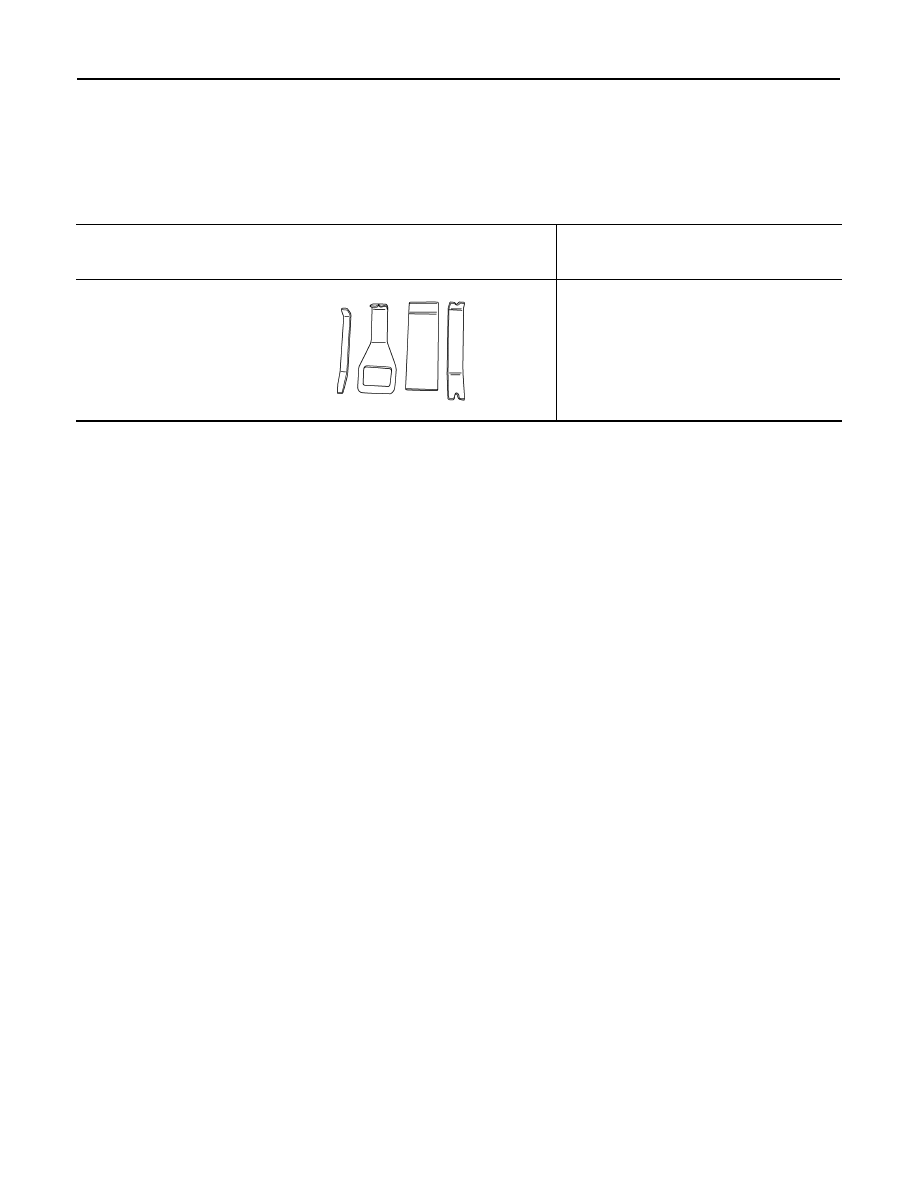
Special Service Tool
INFOID:0000000007355931
The actual shapes of Kent-Moore tools may differ from those of special service tools illustrated here.
Tool number
(Kent-Moore No.)
Tool name
Description
—
(J-46534)
Trim tool set
Removing trim components
AWJIA0483ZZ
August 2012
2012 Pathfinder
POWER WINDOW MAIN SWITCH
PWC-85
< REMOVAL AND INSTALLATION >
C
D
E
F
G
H
I
J
L
M
A
B
PWC
N
O
P
REMOVAL AND INSTALLATION
POWER WINDOW MAIN SWITCH
Removal and Installation
INFOID:0000000007355932
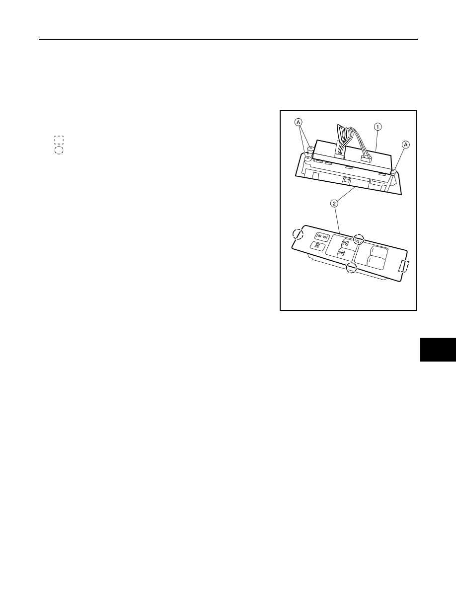
REMOVAL
1. Using a suitable tool, release the metal clip and pawls, then lift
the main power window and door lock/unlock switch and finisher
(2) upward as an assembly.
: Metal clip
: Pawl
CAUTION:
Wrap a cloth around suitable tool to protect components
from damage.
2. Disconnect the harness connectors, then remove the assembly
from front door finisher.
3. Remove the three screws (A) and separate the main power win-
dow and door lock/unlock switch (1) from the switch finisher (2).
INSTALLATION
Installation is in the reverse order of removal.
ALKIA1097ZZ
August 2012
2012 Pathfinder
Нет комментариевНе стесняйтесь поделиться с нами вашим ценным мнением.
Текст