Nissan Pathfinder (2012 year). Instruction — part 609
VARIABLE BLOWER CONTROL
VTL-15
< REMOVAL AND INSTALLATION >
C
D
E
F
G
H
J
K
L
M
A
B
VTL
N
O
P
Removal
1. Disconnect the variable blower control (front) electrical connector.
2. Remove the 2 screws and the variable blower control (front).
Installation
Installation is in the reverse order of removal.
REAR VARIABLE BLOWER CONTROL
Removal
1. Remove the rear heater and cooling unit assembly. Refer to
VTL-18, "Removal and Installation"
2. Disconnect the variable blower control (rear) electrical connector.
3. Remove the 2 screws and the variable blower control (rear).
Installation
Installation is in the reverse order of removal.
August 2012
2012 Pathfinder
VTL-16
< REMOVAL AND INSTALLATION >
FRONT BLOWER MOTOR RESISTOR
FRONT BLOWER MOTOR RESISTOR
Removal and Installation
INFOID:0000000007356277
Blower Motor Resistor - Heater and Cooling Unit Assembly
REMOVAL
1. Disconnect the blower motor resistor electrical connector.
2. Remove the 2 screws and the blower motor resistor.
INSTALLATION
Installation is in the reverse order of removal.
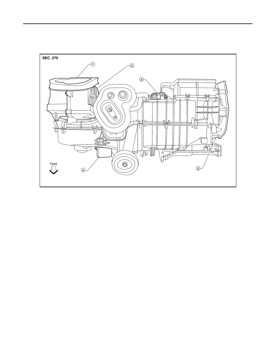
WJIA1312E
1.
Heater and cooling unit assembly
2.
Intake door motor
3.
Air mix door motor
4.
Blower motor resistor
5.
Mode door motor
August 2012
2012 Pathfinder
HEATER & COOLING UNIT ASSEMBLY
VTL-17
< REMOVAL AND INSTALLATION >
C
D
E
F
G
H
J
K
L
M
A
B
VTL
N
O
P
HEATER & COOLING UNIT ASSEMBLY
Component
INFOID:0000000007356278
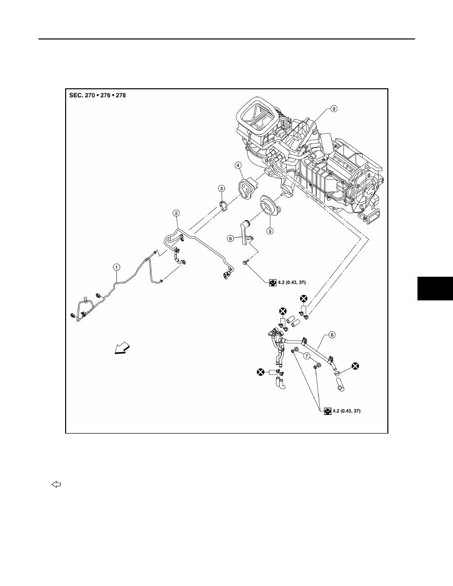
Front Heater and Cooling Unit Assembly
AWIIA1474ZZ
1.
Front high-pressure A/C pipe
2.
Front low-pressure A/C pipe
3.
Front expansion valve
4.
Front heater core and evaporator
pipes grommet
5.
Front A/C drain hose grommet 6.
Front A/C drain hose
7.
Front heater core pipe mounts
8.
Front heater core pipes
9.
Front heater and cooling unit assembly
Vehicle front
August 2012
2012 Pathfinder
VTL-18
< REMOVAL AND INSTALLATION >
HEATER & COOLING UNIT ASSEMBLY
Rear Heater and Cooling Unit Assembly
NOTE:
When removing components such as hoses, tubes/lines, etc., cap or plug openings to prevent fluid from spill-
ing.
Removal and Installation
INFOID:0000000007356279
FRONT HEATER AND COOLING UNIT ASSEMBLY
Removal
CAUTION:
Before servicing, turn the ignition switch off, disconnect both battery terminals, then wait at least
three minutes.
1. Discharge the refrigerant from the A/C system. Refer to
HA-36, "HFC-134a (R-134a) Service Procedure"
2. Drain the coolant from the engine cooling system. Refer to
CO-12, "Changing Engine Coolant"
(VQ40DE),
CO-42, "Changing Engine Coolant"
(VK56DE).
3. Move the front seats to the rearmost position on the seat track.
4. Disconnect the battery negative and positive terminals, then wait at least three minutes.
AWIIA1475ZZ
1.
Rear high- and low-pressure A/C pipes
2.
Rear heater core hoses
3.
Rear high- and low-pressure A/C pipes
cover
4.
Under floor rear high- and low-pressure A/C
and heater core pipes
5.
Rear expansion valve
6.
Rear heater and cooling unit assembly
August 2012
2012 Pathfinder
HEATER & COOLING UNIT ASSEMBLY
VTL-19
< REMOVAL AND INSTALLATION >
C
D
E
F
G
H
J
K
L
M
A
B
VTL
N
O
P
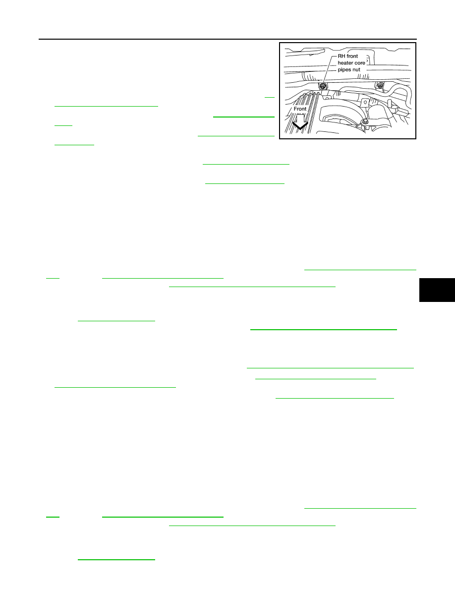
5. Remove the front heater core pipes RH nut.
6. Disconnect the front heater core hoses from the front heater
core.
7. Disconnect the high- and low-pressure A/C pipes from the front
expansion valve.
8. Remove the instrument panel and center console. Refer to
12, "Removal and Installation"
9. Remove the two front floor ducts. Refer to
.
10. Remove the steering column. Refer to
.
11. Disconnect the instrument panel wire harness at the RH and LH in-line connector brackets, and the fuse
block (SMJ) electrical connectors. Refer to
.
12. Remove the covers then remove the three steering member bolts from each side to disconnect the steer-
ing member from the vehicle body. Refer to
.
13. Remove the front heater and cooling unit assembly with it attached to the steering member, from the vehi-
cle.
CAUTION:
Use care not to damage the seats and interior trim panels when removing the front heater and
cooling unit assembly with it attached to the steering member.
14. Remove the front heater and cooling unit assembly from the steering member.
Installation
Installation is in the reverse order of removal.
• Fill the engine cooling system with the specified coolant mixture. Refer to
(VQ40DE),
CO-42, "Changing Engine Coolant"
• Recharge the A/C system. Refer to
HA-36, "HFC-134a (R-134a) Service Procedure"
.
CAUTION:
• Do not reuse O-rings.
• Apple A/C oil to the O-ring of the low-pressure A/C pipe and high-pressure A/C pipe installation.
Refer to
• After charging the refrigerant, check for leaks. Refer to
HA-29, "Checking of Refrigerant Leaks"
REAR HEATER AND COOLING UNIT ASSEMBLY
Removal
1. Discharge the refrigerant from the A/C system. Refer to
HA-36, "HFC-134a (R-134a) Service Procedure"
2. Drain the coolant from the engine cooling system. Refer to
CO-12, "Changing Engine Coolant"
(VQ40DE),
CO-42, "Changing Engine Coolant"
3. Remove the luggage side lower and upper finisher RH. Refer to
INT-25, "Removal and Installation"
4. Disconnect the rear heater core hoses from the rear heater core.
5. Disconnect the rear A/C high- and low-pressure A/C pipes from the rear expansion valve.
6. Disconnect the following electrical connectors:
• Rear blower motor
• Rear variable blower control (rear)
• Rear air mix door motor
7. Disconnect the ducts from the rear heater and cooling unit assembly.
8. Remove the 3 bolts and the rear heater and cooling unit assembly.
Installation
Installation is in the reverse order of removal.
• Fill the engine cooling system with the specified coolant mixture. Refer to
(VQ40DE),
CO-42, "Changing Engine Coolant"
• Recharge the A/C system. Refer to
HA-36, "HFC-134a (R-134a) Service Procedure"
.
CAUTION:
• Do not reuse O-rings.
• Apply A/C oil to the O-ring of the low-pressure A/C pipe and high-pressure A/C pipe for installation.
Refer to
LJIA0165E
August 2012
2012 Pathfinder
VTL-20
< REMOVAL AND INSTALLATION >
HEATER & COOLING UNIT ASSEMBLY
• After charging the refrigerant, check for leaks. Refer to
HA-29, "Checking of Refrigerant Leaks"
.
August 2012
2012 Pathfinder
EVAPORATOR
VTL-21
< REMOVAL AND INSTALLATION >
C
D
E
F
G
H
J
K
L
M
A
B
VTL
N
O
P
EVAPORATOR
Removal and Installation for Front Evaporator
INFOID:0000000007356280
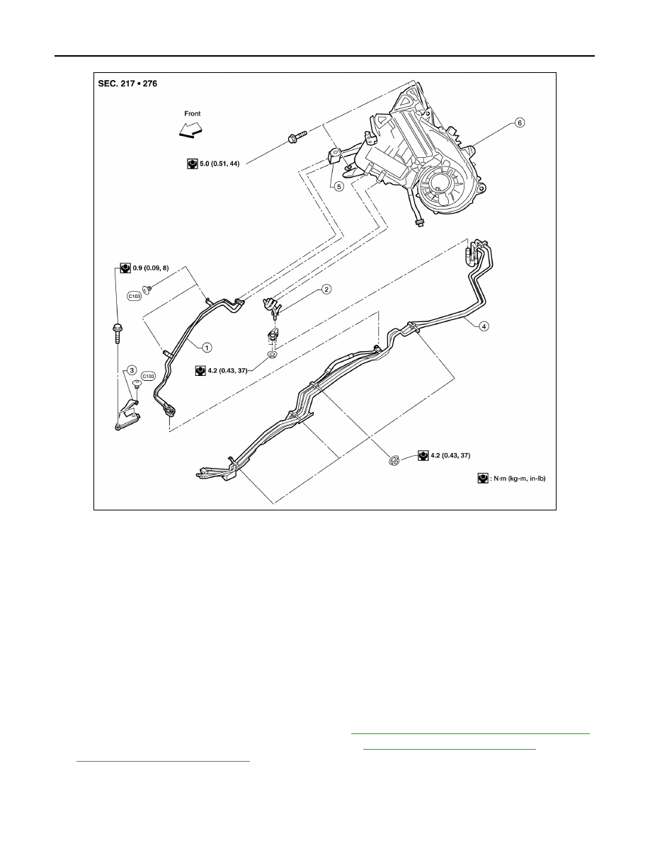
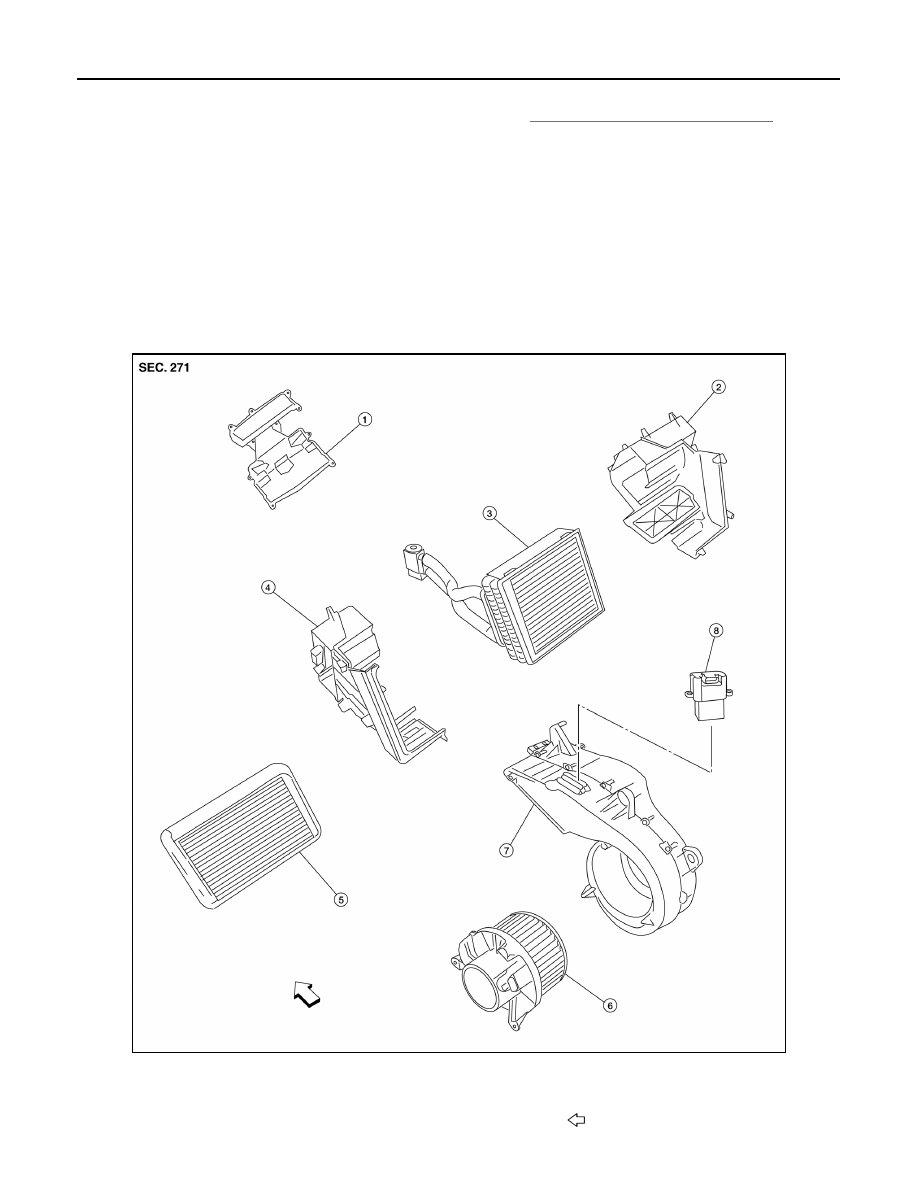
Front Heater and Cooling Unit Assembly
AWIIA1533ZZ
1.
Center ventilator connector duct
2.
Front heater core cover
3.
Intake air case
4.
Front heater core and evaporator
pipes bracket
5.
Front heater core and evaporator
pipes grommet
6.
Front heater core
7.
Upper heater and cooling unit case
8.
Front evaporator and expansion
valve assembly
9.
Lower heater and cooling
unit case
10. Variable blower control (front)
11. Blower motor
August 2012
2012 Pathfinder
VTL-22
< REMOVAL AND INSTALLATION >
EVAPORATOR
REMOVAL
1. Remove the front heater and cooling unit assembly. Refer to
VTL-18, "Removal and Installation"
.
2. Separate the heater and cooling unit case.
3. Remove the front evaporator and expansion valve assembly.
INSTALLATION
Installation is in the reverse order of removal.
CAUTION:
• Do not reuse O-rings.
• Apply A/C oil to the O-rings on the front A/C low-pressure flexible A/C hose and the front high-pres-
sure A/C pipe for installation.
Removal and Installation for Rear Evaporator
INFOID:0000000007356281
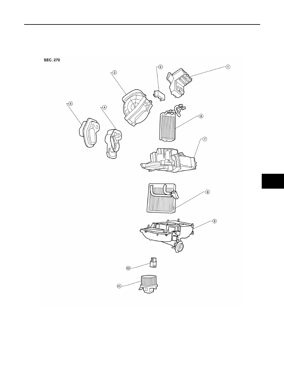
Rear Heater and Cooling Unit Assembly
AWIIA1397ZZ
1.
Front cover
2.
Rear evaporator and heater core case
3.
Rear evaporator
4.
Side cover
5.
Rear heater core
6.
Rear blower motor
7.
Blower motor case
8.
Variable blower control (rear)
Front
August 2012
2012 Pathfinder
Нет комментариевНе стесняйтесь поделиться с нами вашим ценным мнением.
Текст