Nissan Pathfinder (2012 year). Instruction — part 308
ECM
EC-545
< ECU DIAGNOSIS INFORMATION >
[VK56DE]
C
D
E
F
G
H
I
J
K
L
M
A
EC
N
P
O
*1: Accelerator pedal position sensor 2 signal and throttle position sensor 2 signal are converted by ECM internally. Thus, they differ
from ECM terminals voltage signal.
*2: Before measuring the terminal voltage, confirm the battery is fully charged. Refer to
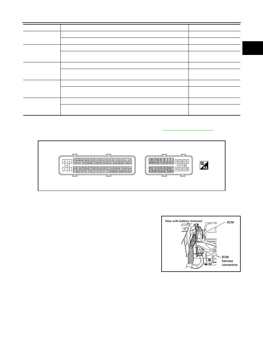
ECM Harness Connector Terminal Layout
INFOID:0000000007358448
ECM Terminal and Reference Value
INFOID:0000000007358449
PREPARATION
ECM is located in the engine room passenger side behind battery.
ECM INSPECTION TABLE
Specification data are reference values and are measured between each terminal and ground.
Pulse signal is measured by CONSULT.
CAUTION:
Never use ECM ground terminals when measuring input/output voltage. Doing so may result in dam-
age to the ECMs transistor. Use a ground other than ECM terminals, such as the ground.
ALT DUTY SIG
• Power generation voltage variable control: Operating
ON
• Power generation voltage variable control: Not operating
OFF
HO2 S2 DIAG1 (B1)
DTC P0139 self-diagnosis (delayed response) has not been performed yet.
INCMP
DTC P0139 self-diagnosis (delayed response) has already been performed
successfully.
CMPLT
HO2 S2 DIAG1 (B2)
DTC P0159 self-diagnosis (delayed response) has not been performed yet.
INCMP
DTC P0159 self-diagnosis (delayed response) has already been performed
successfully.
CMPLT
HO2 S2 DIAG2 (B1)
DTC P0139 self-diagnosis (slow response) has not been performed yet.
INCMP
DTC P0139 self-diagnosis (slow response) has already been performed suc-
cessfully.
CMPLT
HO2 S2 DIAG2 (B2)
DTC P0159 self-diagnosis (slow response) has not been performed yet.
INCMP
DTC P0159 self-diagnosis (slow response) has already been performed suc-
cessfully.
CMPLT
MONITOR ITEM
CONDITION
SPECIFICATION
PBIB3368E
BBIA0386E
August 2012
2012 Pathfinder
EC-546
< ECU DIAGNOSIS INFORMATION >
[VK56DE]
ECM
TER-
MI-
NAL
NO.
WIRE
COLOR
ITEM
CONDITION
DATA (DC Voltage)
1
BR
ECM ground
[Engine is running]
• Idle speed
Body ground
2
G
A/F sensor 1 heater (bank 1)
[Engine is running]
•
Warm-up condition
• Idle speed
(More than 140 seconds after starting
engine)
Approximately 2.9 - 8.8 V
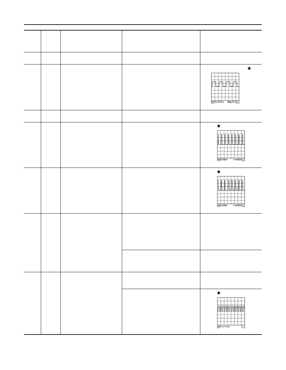
3
V
Throttle control motor power sup-
ply
[Ignition switch: ON]
BATTERY VOLTAGE
(11 - 14 V)
4
L/W
Throttle control motor (Close)
[Ignition switch: ON]
• Engine: Stopped
• Selector lever: D position
• Accelerator pedal: Fully released
0 - 14 V
5
L/B
Throttle control motor (Open)
[Ignition switch: ON]
• Engine: Stopped
• Selector lever: D position
• Accelerator pedal: Fully depressed
0 - 14 V
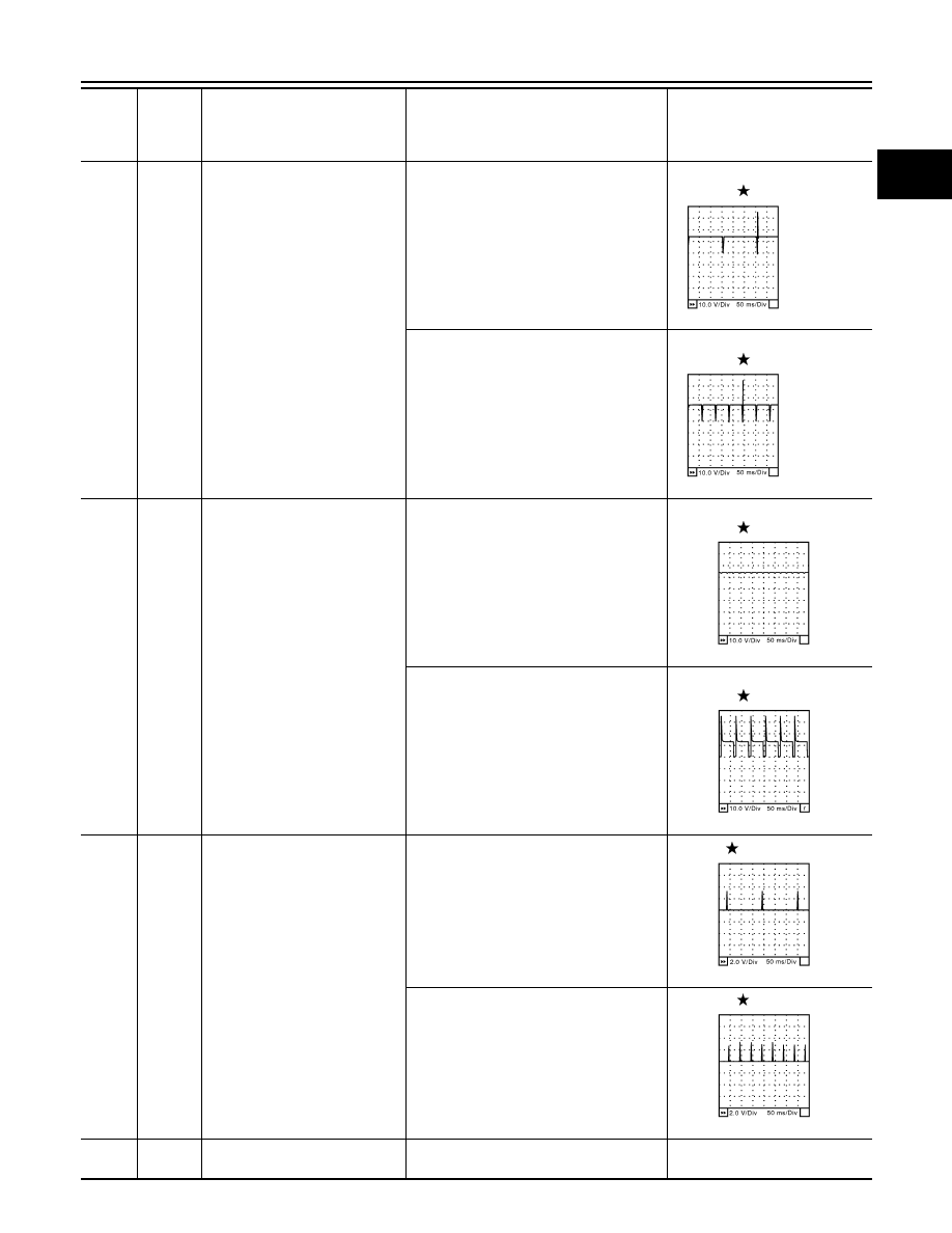
6
R
Heated oxygen sensor 2 heater
(bank 1)
[Engine is running]
• Engine speed: Below 3,600 rpm after the
following conditions are met.
- Engine: After warming up
- Keeping the engine speed between
3,500 and 4,000 rpm for 1 minute and at
idle for 1 minute under no load
0 - 1.0 V
[Ignition switch: ON]
• Engine: Stopped
[Engine is running]
• Engine speed: Above 3,600 rpm
BATTERY VOLTAGE
(11 - 14 V)
10
W
Intake valve timing control sole-
noid valve (bank 1)
[Engine is running]
•
Warm-up condition
• Idle speed
BATTERY VOLTAGE
(11 - 14 V)
[Engine is running]
•
Warm-up condition
• Engine speed: 2,000rpm
7 - 12 V
PBIA8148J
PBIB1104E
PBIB1105E
PBIB1790E
August 2012
2012 Pathfinder
ECM
EC-547
< ECU DIAGNOSIS INFORMATION >
[VK56DE]
C
D
E
F
G
H
I
J
K
L
M
A
EC
N
P
O
11
LG
Intake valve timing control sole-
noid valve (bank 2)
[Engine is running]
•
Warm-up condition
• Idle speed
BATTERY VOLTAGE
(11 - 14 V)
[Engine is running]
•
Warm-up condition
• Engine speed: 2,000rpm
7 - 12 V
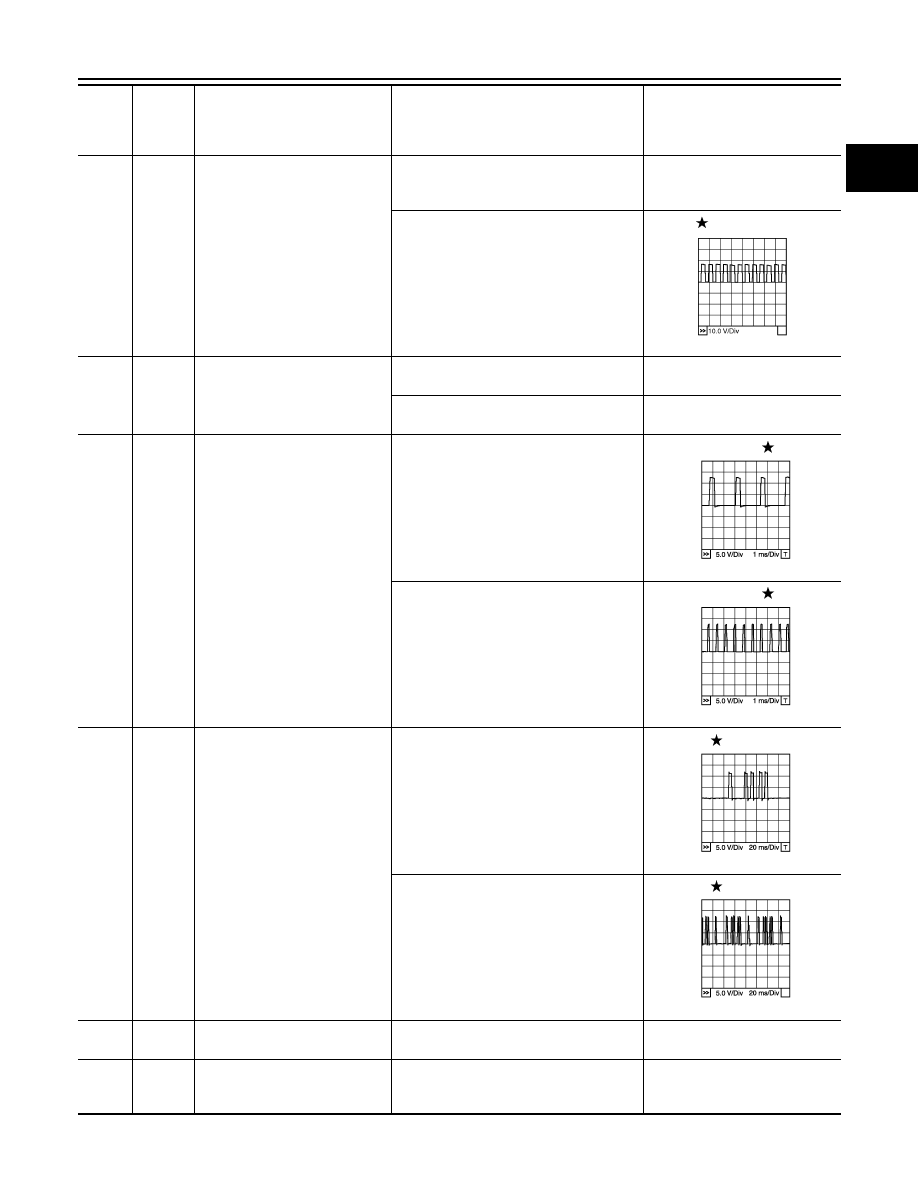
12
P
Power steering pressure sensor
[Engine is running]
• Steering wheel: Being turned
0.5 - 4.5 V
[Engine is running]
• Steering wheel: Not being turned
0.4 - 0.8 V
13
G
Crankshaft position sensor
(POS)
[Engine is running]
•
Warm-up condition
• Idle speed
NOTE:
The pulse cycle changes depending on
rpm at idle
Approximately 10 V
[Engine is running]
• Engine speed: 2,000 rpm
Approximately 10 V
14
SB
Camshaft position sensor
(PHASE)
[Engine is running]
•
Warm-up condition
• Idle speed
NOTE:
The pulse cycle changes depending on
rpm at idle
1.0 - 4.0 V
[Engine is running]
• Engine speed: 2,000 rpm
1.0 - 4.0 V
15
W
Knock sensor (bank 1)
[Engine is running]
• Idle speed
Approximately 2.5 V
16
L
A/F sensor 1 (bank 2)
[Engine is running]
•
Warm-up condition
• Engine speed: 2,000 rpm
Approximately 1.8 V
Output voltage varies with air fuel
ratio.
TER-
MI-
NAL
NO.
WIRE
COLOR
ITEM
CONDITION
DATA (DC Voltage)
PBIB1790E
PBIB1041E
PBIB1042E
PBIB1039E
PBIB1040E
August 2012
2012 Pathfinder
EC-548
< ECU DIAGNOSIS INFORMATION >
[VK56DE]
ECM
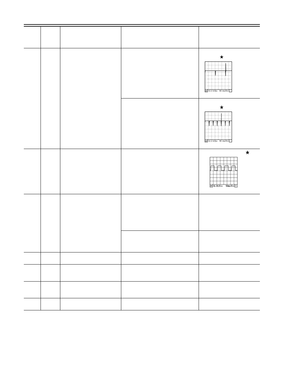
21
22
23
44
L
V
G
L
Fuel injector No. 5
Fuel injector No. 3
Fuel injector No. 1
Fuel injector No. 7
[Engine is running]
•
Warm-up condition
• Idle speed
NOTE:
The pulse cycle changes depending on
rpm at idle
BATTERY VOLTAGE
(11 - 14 V)
[Engine is running]
•
Warm-up condition
• Engine speed: 2,000 rpm
BATTERY VOLTAGE
(11 - 14 V)
24
43
G
G
A/F sensor 1 heater (bank 2)
[Engine is running]
•
Warm-up condition
• Idle speed
(More than 140 seconds after starting
engine)
Approximately 2.9 - 8.8 V
25
P
Heated oxygen sensor 2 heater
(bank 2)
[Engine is running]
• Engine speed: Below 3,600 rpm after the
following conditions are met.
- Engine: After warming up
- Keeping the engine speed between
3,500 and 4,000 rpm for 1 minute and at
idle for 1 minute under no load
0 - 1.0 V
[Ignition switch: ON]
• Engine: Stopped
[Engine is running]
• Engine speed: Above 3,600 rpm
BATTERY VOLTAGE
(11 - 14 V)
32
W
EVAP control system pressure
sensor
[Ignition switch: ON]
Approximately 1.8 - 4.8 V
34
BR
Intake air temperature sensor
[Engine is running]
Approximately 0 - 4.8 V
Output voltage varies with intake
air temperature.
35
O
A/F sensor 1 (bank 1)
[Engine is running]
•
Warm-up condition
• Engine speed: 2,000 rpm
Approximately 1.8 V
Output voltage varies with air fuel
ratio.
36
W
Knock sensor (bank 2)
[Engine is running]
• Idle speed
Approximately 2.5 V
TER-
MI-
NAL
NO.
WIRE
COLOR
ITEM
CONDITION
DATA (DC Voltage)
SEC984C
SEC985C
PBIA8148J
August 2012
2012 Pathfinder
ECM
EC-549
< ECU DIAGNOSIS INFORMATION >
[VK56DE]
C
D
E
F
G
H
I
J
K
L
M
A
EC
N
P
O
40
41
42
63
V
R
O
W
Fuel injector No. 6
Fuel injector No. 4
Fuel injector No. 2
Fuel injector No. 8
[Engine is running]
•
Warm-up condition
• Idle speed
NOTE:
The pulse cycle changes depending on
rpm at idle
BATTERY VOLTAGE
(11 - 14 V)
[Engine is running]
•
Warm-up condition
• Engine speed: 2,000 rpm
BATTERY VOLTAGE
(11 - 14 V)
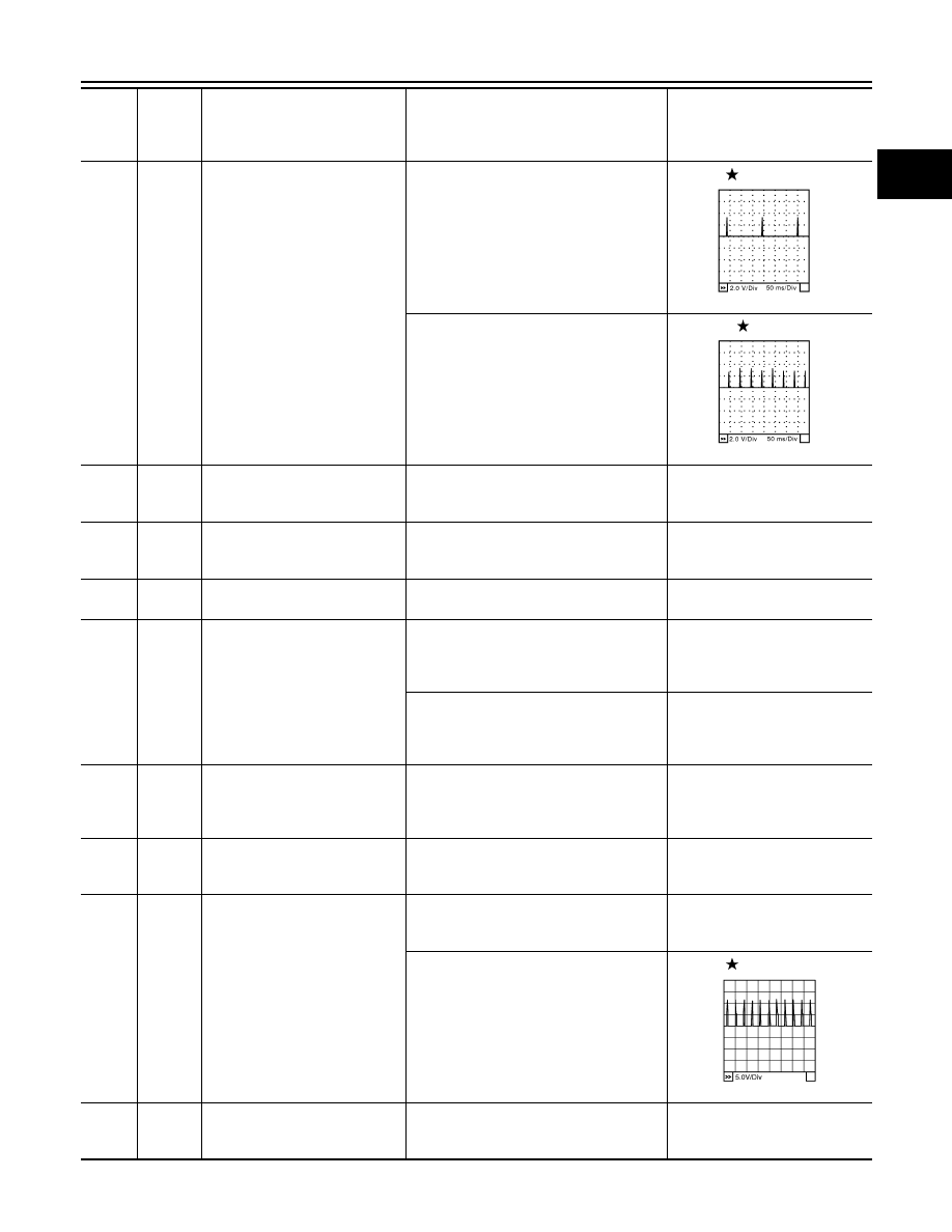
45
R
EVAP canister purge volume
control solenoid valve
[Engine is running]
• Idle speed
• Accelerator pedal: Not depressed even
slightly, after engine starting
BATTERY VOLTAGE
(11 - 14 V)
[Engine is running]
• Engine speed: About 2,000 rpm (More
than 100 seconds after starting engine)
BATTERY VOLTAGE
(11 - 14 V)
46
60
61
62
LG
V
L
Y
Ignition signal No. 7
Ignition signal No. 5
Ignition signal No. 3
Ignition signal No. 1
[Engine is running]
•
Warm-up condition
• Idle speed
NOTE:
The pulse cycle changes depending on
rpm at idle
0 - 0.3 V
[Engine is running]
•
Warm-up condition
• Engine speed: 2,500 rpm
0.1 - 0.6 V
47
L
Sensor power supply
(Throttle position sensor)
[Ignition switch: ON]
Approximately 5 V
TER-
MI-
NAL
NO.
WIRE
COLOR
ITEM
CONDITION
DATA (DC Voltage)
SEC984C
SEC985C
SEC990C
SEC991C
SEC986C
SEC987C
August 2012
2012 Pathfinder

EC-550
< ECU DIAGNOSIS INFORMATION >
[VK56DE]
ECM
48
SB
Sensor power supply
(EVAP control system pressure
sensor)
[Ignition switch: ON]
Approximately 5 V
49
P
Sensor power supply
(Refrigerant pressure sensor)
[Ignition switch: ON]
Approximately 5 V
50
W
Throttle position sensor 1
[Ignition switch: ON]
• Engine: Stopped
• Selector lever: D position
• Accelerator pedal: Fully released
More than 0.36 V
[Ignition switch: ON]
• Engine: Stopped
• Selector lever: D position
• Accelerator pedal: Fully depressed
Less than 4.75 V
51
P
Mass air flow sensor
[Engine is running]
•
Warm-up condition
• Idle speed
1.0 - 1.3 V
[Engine is running]
•
Warm-up condition
• Engine speed: 2,500 rpm
1.7 - 2.1 V
53
L
Intake valve timing control posi-
tion sensor (Bank 2)
[Engine is running]
•
Warm-up condition
• Idle speed
0 - 1.0 V
[Engine is running]
• Engine speed: 2,000 rpm
0 - 1.0 V
55
G
Heated oxygen sensor 2 (bank 1)
[Engine is running]
• Revving engine from idle to 3,000 rpm
quickly after the following conditions are
met.
- Engine: After warming up
- Keeping the engine speed between
3,500 and 4,000 rpm for 1 minute and at
idle for 1 minute under no load
0 - Approximately 1.0 V
56
W
A/F sensor 1 (bank 1)
[Ignition switch: ON]
Approximately 2.2 V
TER-
MI-
NAL
NO.
WIRE
COLOR
ITEM
CONDITION
DATA (DC Voltage)
PBIB2046E
August 2012
2012 Pathfinder
ECM
EC-551
< ECU DIAGNOSIS INFORMATION >
[VK56DE]
C
D
E
F
G
H
I
J
K
L
M
A
EC
N
P
O
65
79
80
81
GR
P
GR
G
Ignition signal No. 8
Ignition signal No. 6
Ignition signal No. 4
Ignition signal No. 2
[Engine is running]
•
Warm-up condition
• Idle speed
NOTE:
The pulse cycle changes depending on
rpm at idle
0 - 0.3 V
[Engine is running]
•
Warm-up condition
• Engine speed: 2,500 rpm
0.1 - 0.6 V
66
B
Sensor ground
(Throttle position sensor)
[Engine is running]
•
Warm-up condition
• Idle speed
Approximately 0 V
67
B
Sensor ground
[Engine is running]
•
Warm-up condition
• Idle speed
Approximately 0 V
68
G
Sensor power supply
(PSP sensor)
[Ignition switch: ON]
Approximately 5 V
69
R
Throttle position sensor 2
[Ignition switch: ON]
• Engine: Stopped
• Selector lever: D position
• Accelerator pedal: Fully released
Less than 4.75 V
[Ignition switch: ON]
• Engine: Stopped
• Selector lever: D position
• Accelerator pedal: Fully depressed
More than 0.36 V
70
BR
Refrigerant pressure sensor
[Engine is running]
•
Warm-up condition
• Both A/C switch and blower fan switch:
ON (Compressor: Operates.)
1.0 - 4.0 V
71
R
Battery current sensor
[Engine is running]
• Battery: Fully charged*
• Idle speed
Approximately 2.6 - 3.5 V
72
Y
Intake valve timing control posi-
tion sensor (Bank 1)
[Engine is running]
•
Warm-up condition
• Idle speed
0 -1.0 V
[Engine is running]
• Engine speed: 2,000rpm
0 - 1.0 V
73
Y
Engine coolant temperature sen-
sor
[Engine is running]
Approximately 0 - 4.8 V
Output voltage varies with engine
coolant temperature.
TER-
MI-
NAL
NO.
WIRE
COLOR
ITEM
CONDITION
DATA (DC Voltage)
SEC986C
SEC987C
PBIB2046E
August 2012
2012 Pathfinder

EC-552
< ECU DIAGNOSIS INFORMATION >
[VK56DE]
ECM
74
SB
Heated oxygen sensor 2 (bank 2)
[Engine is running]
• Revving engine from idle to 3,000 rpm
quickly after the following conditions are
met.
- Engine: After warming up
- Keeping the engine speed between
3,500 and 4,000 rpm for 1 minute and at
idle for 1 minute under no load
0 - Approximately 1.0 V
75
P
A/F sensor 1 (bank 2)
[Ignition switch: ON]
Approximately 2.2 V
78
GR
Sensor ground
(Heated oxygen sensor 2)
[Engine is running]
•
Warm-up condition
• Idle speed
Approximately 0 V
82
B
Sensor ground
(APP sensor 1)
[Engine is running]
•
Warm-up condition
• Idle speed
Approximately 0 V
83
B
Sensor ground
(APP sensor 2)
[Engine is running]
•
Warm-up condition
• Idle speed
Approximately 0 V
85
W
Data link connector
—
—
86
P
CAN communication line
—
—
90
L
Sensor power supply
(APP sensor 1)
[Ignition switch: ON]
Approximately 5 V
91
G
Sensor power supply
(APP sensor 2)
[Ignition switch: ON]
Approximately 5 V
94
L
CAN communication line
—
—
98
GR
Accelerator pedal position sen-
sor 2
[Ignition switch: ON]
• Engine: Stopped
• Accelerator pedal: Fully released
0.28 - 0.48 V
[Ignition switch: ON]
• Engine: Stopped
• Accelerator pedal: Fully depressed
More than 2.0 V
99
SB
ASCD steering switch
[Ignition switch: ON]
• ASCD steering switch: OFF
Approximately 4 V
[Ignition switch: ON]
• MAIN switch: Pressed
Approximately 0V
[Ignition switch: ON]
• CANCEL switch: Pressed
Approximately 1 V
[Ignition switch: ON]
• RESUME/ACCELERATE switch:
Pressed
Approximately 3 V
[Ignition switch: ON]
• SET/COAST switch: Pressed
Approximately 2 V
101
LG
Stop lamp switch
[Ignition switch: OFF]
• Brake pedal: Fully released
Approximately 0 V
[Ignition switch: OFF]
• Brake pedal: Slightly depressed
BATTERY VOLTAGE
(11 - 14 V)
102
G
PNP signal
[Ignition switch: ON]
• Selector lever: P or N position
Approximately 0 V
[Ignition switch: ON]
• Selector lever: Except above position
BATTERY VOLTAGE
(11 - 14 V)
TER-
MI-
NAL
NO.
WIRE
COLOR
ITEM
CONDITION
DATA (DC Voltage)
August 2012
2012 Pathfinder
Нет комментариевНе стесняйтесь поделиться с нами вашим ценным мнением.
Текст