Nissan Pathfinder (2012 year). Instruction — part 455
LAN-68
< WIRING DIAGRAM >
[CAN]
CAN SYSTEM
ABMIA3323GB
August 2012
2012 Pathfinder
LAN
CAN COMMUNICATION SYSTEM
LAN-69
< DTC/CIRCUIT DIAGNOSIS >
[CAN]
C
D
E
F
G
H
I
J
K
L
B
A
O
P
N
DTC/CIRCUIT DIAGNOSIS
CAN COMMUNICATION SYSTEM
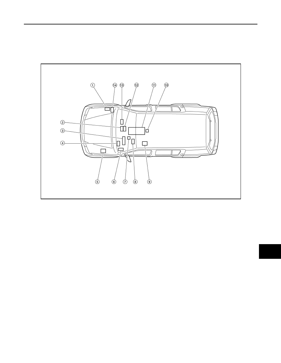
Component Parts Location
INFOID:0000000007354992
1.
ECM
E7: VK engine models
E16: VQ engine models
2.
AV control unit
M48: With BOSE audio system with
navigation system
M70: Without BOSE audio system
without navigation system
M135: With mid audio system
3.
Combination meter M24
4.
BCM M18
5.
ABS actuator and electric unit (con-
trol unit)
E125: VQ engine models
E127: VK engine models
6.
Transfer control unit
M152: All-mode 4WD models
M165: Part time 4WD models
7.
Data link connector M22
8.
Steering angle sensor M47
9.
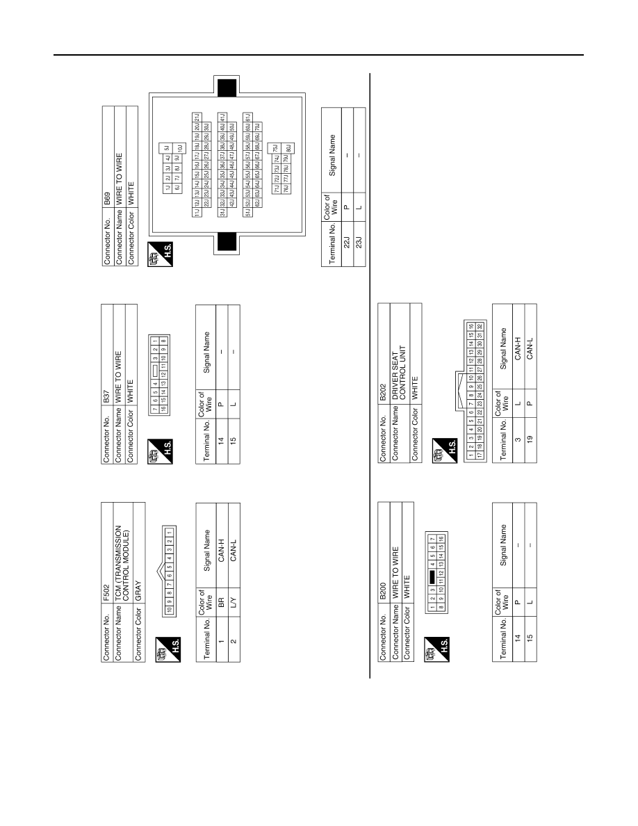
Driver seat control unit B202
10. Air bag diagnosis sensor unit M35
11. A/T assembly F9
12. A/C auto amp. M50
13. Intelligent Key unit M164
14. IPDM E/R E122
AWMIA0018ZZ
August 2012
2012 Pathfinder
LAN-70
< DTC/CIRCUIT DIAGNOSIS >
[CAN]
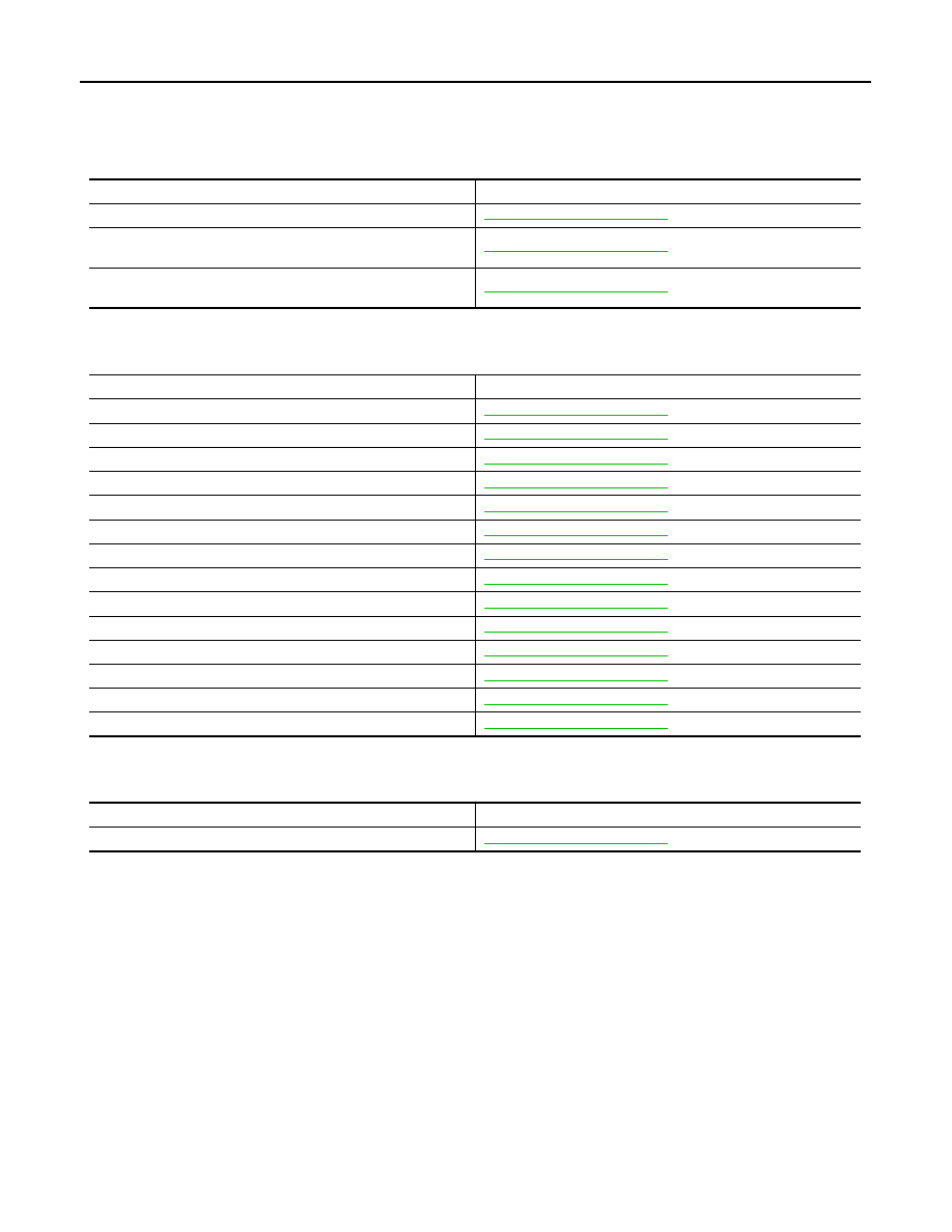
MALFUNCTION AREA CHART
MALFUNCTION AREA CHART
Main Line
INFOID:0000000007354993
Branch Line
INFOID:0000000007354994
Short Circuit
INFOID:0000000007354995
Malfunction area
Reference
Main line between TCM and air bag diagnosis sensor unit
Main line between air bag diagnosis sensor unit and data link
connector
Main line between data link connector and ABS actuator and
electric unit (control unit)
Malfunction area
Reference
ECM branch line circuit
TCM branch line circuit
Air bag diagnosis sensor unit branch line circuit
AV control unit branch line circuit
Intelligent Key unit branch line circuit
Transfer control unit branch line circuit
Driver seat control unit branch line circuit
BCM branch line circuit
Data link connector branch line circuit
A/C auto amp. branch line circuit
Combination meter branch line circuit
Steering angle sensor branch line circuit
ABS actuator and electric unit (control unit) branch line circuit
IPDM E/R branch line circuit
Malfunction area
Reference
CAN communication circuit
August 2012
2012 Pathfinder
LAN
MAIN LINE BETWEEN TCM AND A-BAG CIRCUIT
LAN-71
< DTC/CIRCUIT DIAGNOSIS >
[CAN]
C
D
E
F
G
H
I
J
K
L
B
A
O
P
N
MAIN LINE BETWEEN TCM AND A-BAG CIRCUIT
Diagnosis Procedure
INFOID:0000000007354996
1.
CHECK CONNECTOR
1. Turn the ignition switch OFF.
2. Disconnect the battery cable from the negative terminal.
3. Check the following terminals and connectors for damage, bend and loose connection (connector side
and harness side).
-
Harness connector F14
-
Harness connector E5
-
Harness connector E152
-
Harness connector M31
Is the inspection result normal?
YES
>> GO TO 2.
NO
>> Repair the terminal and connector.
2.
CHECK HARNESS CONTINUITY (OPEN CIRCUIT)
1. Disconnect the following harness connectors.
-
A/T assembly
-
Harness connectors F14 and E5
2. Check the continuity between the A/T assembly harness connector and the harness connector.
Is the inspection result normal?
YES
>> GO TO 3.
NO
>> Repair the main line between the A/T assembly and the harness connector F14.
3.
CHECK HARNESS CONTINUITY (OPEN CIRCUIT)
1. Disconnect the harness connectors E152 and M31.
2. Check the continuity between the harness connectors.
Is the inspection result normal?
YES
>> GO TO 4.
NO
>> Repair the main line between the harness connectors E5 and E152.
4.
CHECK HARNESS CONTINUITY (OPEN CIRCUIT)
Check the continuity between the harness connector and the data link connector.
Is the inspection result normal?
YES (Present error)>>Check the following items again.
• Decision of CAN system type.
• Not received CONSULT data (SELF-DIAG RESULTS, CAN DIAG SUPPORT MNTR).
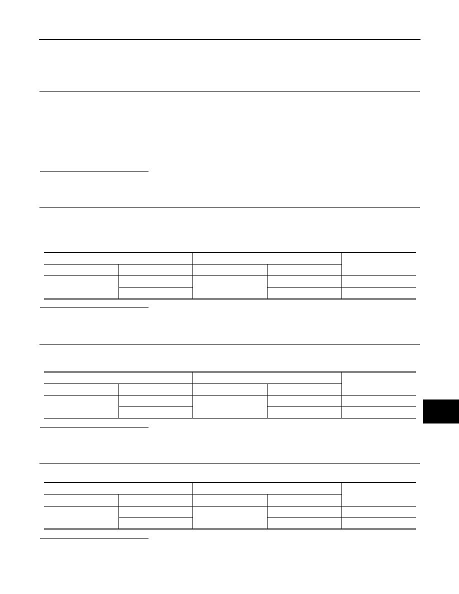
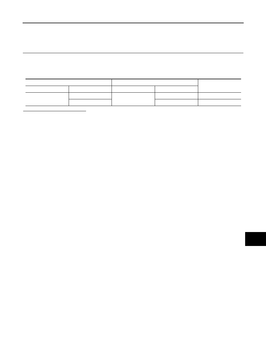
A/T assembly harness connector
Harness connector
Continuity
Connector No.
Terminal No.
Connector No.
Terminal No.
F9
3
F14
2
Existed
8
3
Existed
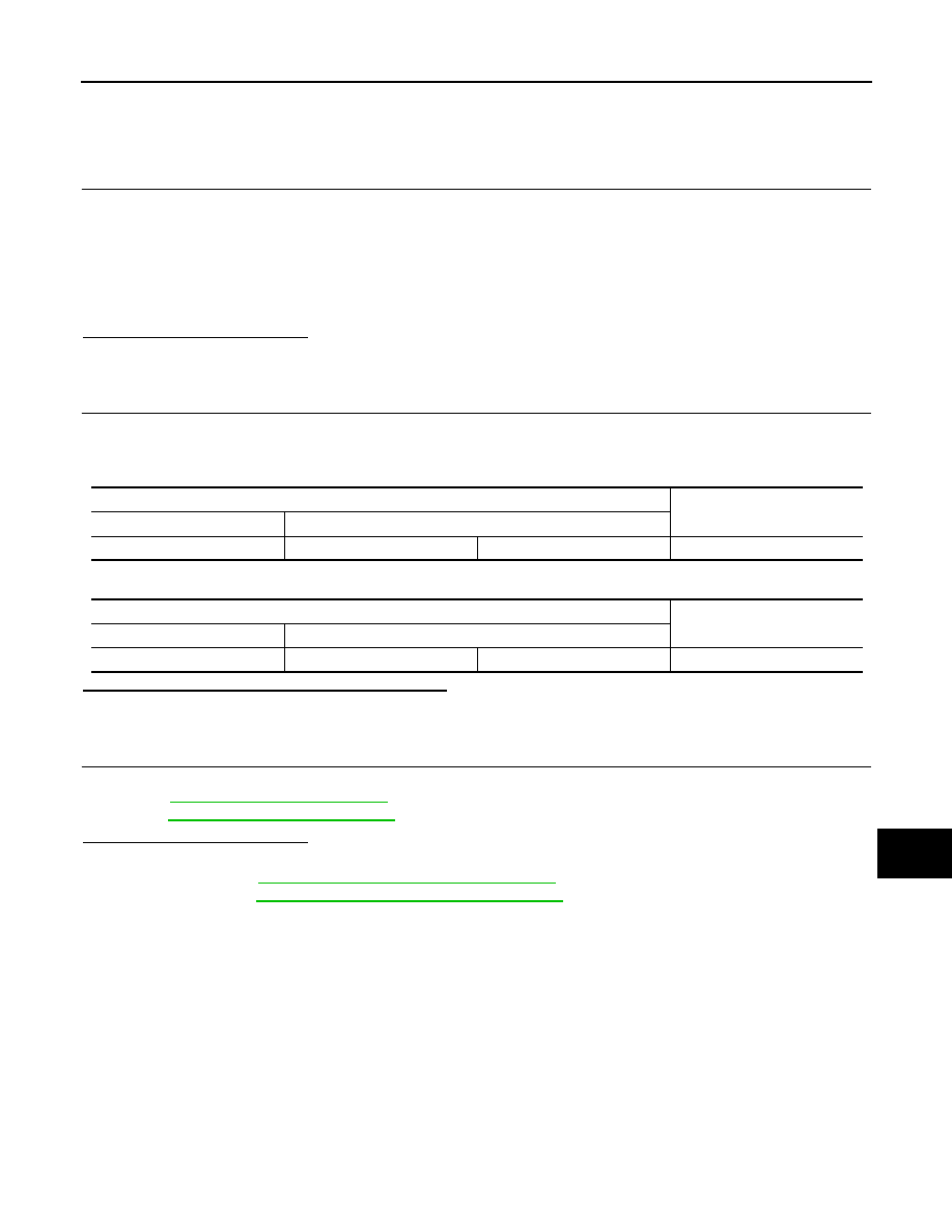
Harness connector
Harness connector
Continuity
Connector No.
Terminal No.
Connector No.
Terminal No.
E5
2
E152
52G
Existed
3
51G
Existed
Harness connector
Data link connector
Continuity
Connector No.
Terminal No.
Connector No.
Terminal No.
M31
52G
M22
6
Existed
51G
14
Existed
August 2012
2012 Pathfinder
LAN-72
< DTC/CIRCUIT DIAGNOSIS >
[CAN]
MAIN LINE BETWEEN TCM AND A-BAG CIRCUIT
• Procedure for detecting root cause.
YES (Past error)>>Error was detected in the main line between the TCM and the air bag diagnosis sensor
unit.
NO
>> Repair the main line between the harness connector M31 and the air bag diagnosis sensor unit.
August 2012
2012 Pathfinder
LAN
MAIN LINE BETWEEN A-BAG AND DLC CIRCUIT
LAN-73
< DTC/CIRCUIT DIAGNOSIS >
[CAN]
C
D
E
F
G
H
I
J
K
L
B
A
O
P
N
MAIN LINE BETWEEN A-BAG AND DLC CIRCUIT
Diagnosis Procedure
INFOID:0000000007354997
1.
CHECK HARNESS CONTINUITY (OPEN CIRCUIT)
1. Turn the ignition switch OFF.
2. Disconnect the battery cable from the negative terminal.
3. Disconnect the harness connectors E152 and M31.
4. Check the continuity between the harness connector and the data link connector.
Is the inspection result normal?
YES (Present error)>>Check the following items again.
• Decision of CAN system type.
• Not received CONSULT data (SELF-DIAG RESULTS, CAN DIAG SUPPORT MNTR).
• Procedure for detecting root cause.
YES (Past error)>>Error was detected in the main line between the air bag diagnosis sensor unit and the
data link connector.
NO
>> Repair the main line between the air bag diagnosis sensor unit and the data link connector.
Harness connector
Data link connector
Continuity
Connector No.
Terminal No.
Connector No.
Terminal No.
M31
52G
M22
6
Existed
51G
14
Existed
August 2012
2012 Pathfinder

LAN-74
< DTC/CIRCUIT DIAGNOSIS >
[CAN]
MAIN LINE BETWEEN DLC AND ABS CIRCUIT
MAIN LINE BETWEEN DLC AND ABS CIRCUIT
Diagnosis Procedure
INFOID:0000000007354998
1.
CHECK CONNECTOR
1. Turn the ignition switch OFF.
2. Disconnect the battery cable from the negative terminal.
3. Check the following terminals and connectors for damage, bend and loose connection (connector side
and harness side).
-
Harness connector M91
-
Harness connector E26
Is the inspection result normal?
YES
>> GO TO 2.
NO
>> Repair the terminal and connector.
2.
CHECK HARNESS CONTINUITY (OPEN CIRCUIT)
1. Disconnect the harness connectors M91 and E26.
2. Check the continuity between the data link connector and the harness connector.
Is the inspection result normal?
YES
>> GO TO 3.
NO
>> Repair the main line between the data link connector and the harness connector M91.
3.
CHECK HARNESS CONTINUITY (OPEN CIRCUIT)
1. Disconnect the connector of ABS actuator and electric unit (control unit).
2. Check the continuity between the harness connector and the ABS actuator and electric unit (control unit)
harness connector.
-
VQ engine models
-
VK engine models
Is the inspection result normal?
YES (Present error)>>Check the following items again.
• Decision of CAN system type.
• Not received CONSULT data (SELF-DIAG RESULTS, CAN DIAG SUPPORT MNTR).
• Procedure for detecting root cause.
YES (Past error)>>Error was detected in the main line between the data link connector and the ABS actuator
and electric unit (control unit).
NO
>> Repair the main line between the harness connector E26 and the ABS actuator and electric unit
(control unit).
Data link connector
Harness connector
Continuity
Connector No.
Terminal No.
Connector No.
Terminal No.
M22
6
M91
11
Existed
14
10
Existed
Harness connector
ABS actuator and electric unit (control unit)
harness connector
Continuity
Connector No.
Terminal No.
Connector No.
Terminal No.
E26
11
E125
12
Existed
10
13
Existed
Harness connector
ABS actuator and electric unit (control unit)
harness connector
Continuity
Connector No.
Terminal No.
Connector No.
Terminal No.
E26
11
E127
11
Existed
10
15
Existed
August 2012
2012 Pathfinder
LAN
ECM BRANCH LINE CIRCUIT
LAN-75
< DTC/CIRCUIT DIAGNOSIS >
[CAN]
C
D
E
F
G
H
I
J
K
L
B
A
O
P
N
ECM BRANCH LINE CIRCUIT
Diagnosis Procedure
INFOID:0000000007354999
1.
CHECK CONNECTOR
1. Turn the ignition switch OFF.
2. Disconnect the battery cable from the negative terminal.
3. Check the following terminals and connectors for damage, bend and loose connection (unit side and con-
nector side).
-
ECM
-
Harness connector E2
-
Harness connector F32
Is the inspection result normal?
YES
>> GO TO 2.
NO
>> Repair the terminal and connector.
2.
CHECK HARNESS FOR OPEN CIRCUIT
1. Disconnect the connector of ECM.
2. Check the resistance between the ECM harness connector terminals.
-
VQ engine models
-
VK engine models
Is the measurement value within the specification?
YES
>> GO TO 3.
NO
>> Repair the ECM branch line.
3.
CHECK POWER SUPPLY AND GROUND CIRCUIT
Check the power supply and the ground circuit of the ECM. Refer to the following.
• VQ40DE:
• VK56DE:
Is the inspection result normal?
YES (Present error)>>Replace the ECM. Refer to the following.
• VQ40DE:
EC-24, "Procedure After Replacing ECM"
• VK56DE:
EC-596, "Procedure After Replacing ECM"
YES (Past error)>>Error was detected in the ECM branch line.
NO
>> Repair the power supply and the ground circuit.
ECM harness connector
Resistance (
Ω
)
Connector No.
Terminal No.
E16
94
86
Approx. 108 – 132
ECM harness connector
Resistance (
Ω
)
Connector No.
Terminal No.
E7
94
86
Approx. 108 – 132
August 2012
2012 Pathfinder
Нет комментариевНе стесняйтесь поделиться с нами вашим ценным мнением.
Текст