Nissan Pathfinder (2012 year). Instruction — part 355
COOLING FAN
EC-921
< DTC/CIRCUIT DIAGNOSIS >
[VK56DE]
C
D
E
F
G
H
I
J
K
L
M
A
EC
N
P
O
COOLING FAN
Description
INFOID:0000000007358838
COMPONENT DESCRIPTION
Cooling Fan Motor
The cooling fan operates at each speed when the current flows in the cooling fan motor as per the following.
Diagnosis Procedure
INFOID:0000000007358839
1.
CHECK IPDM E/R POWER SUPPLY AND GROUND CIRCUIT
OK or NG
OK
>> GO TO 2.
NG
>> Follow the instructions on
.
2.
CHECK COOLING FAN MOTOR POWER SUPPLY CIRCUIT FOR OPEN AND SHORT
1. Turn ignition switch OFF.
2. Disconnect IPDM E/R harness connector E120.
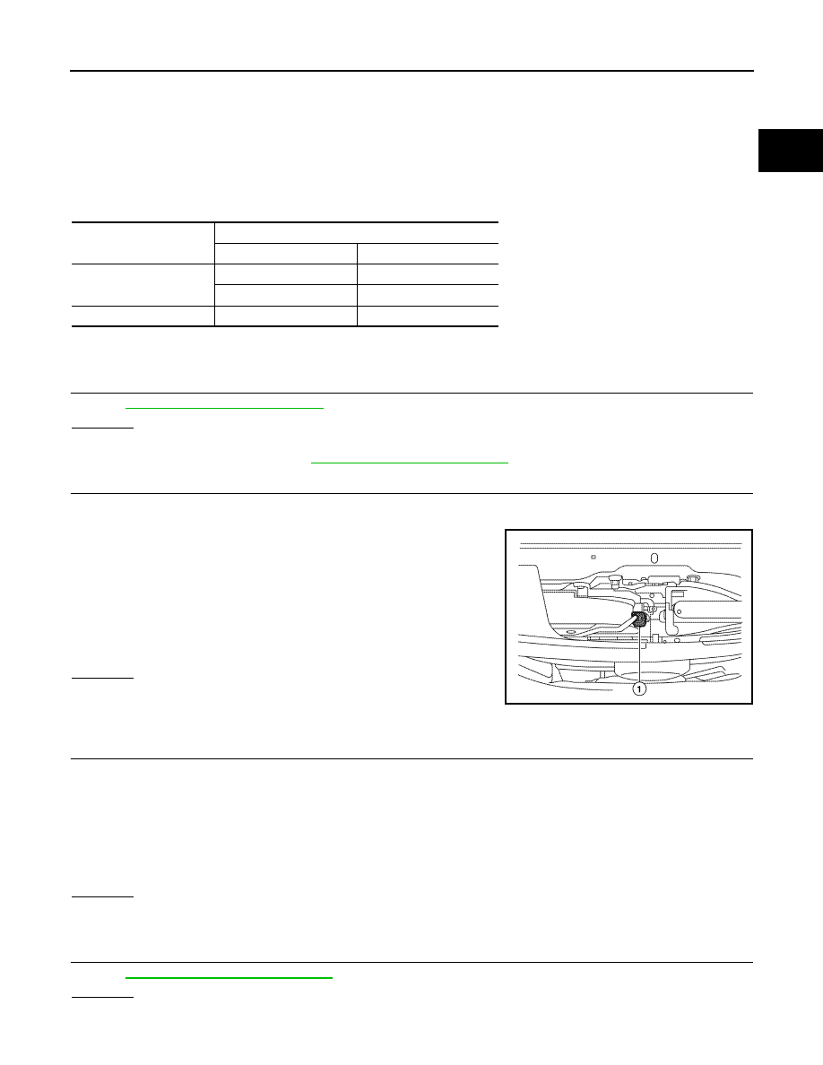
3. Disconnect cooling fan motor (1) harness connector.
4. Check harness continuity between the following terminals;
cooling fan motor terminal 1 and IPDM E/R terminal 20,
cooling fan motor terminal 2 and IPDM E/R terminal 24.
Refer to Wiring Diagram.
5. Also check harness for short to ground and short to power.
OK or NG
OK
>> GO TO 3.
NG
>> Repair open circuit or short to ground or short to power
in harness or connectors.
3.
CHECK COOLING FAN MOTER GROUND CIRCUIT FOR OPEN OR SHORT
1. Check harness continuity between the following terminals;
cooling fan motor terminal 3 and ground,
cooling fan motor terminal 4 and ground.
Refer to Wiring Diagram.
2. Also check harness for short to power.
OK or NG
OK
>> GO TO 4.
NG
>> Repair open circuit or short to power in harness or connectors.
4.
CHECK COOLING FAN MOTOR
EC-922, "Component Inspection"
OK or NG
OK
>> GO TO 5.
Cooling fan speed
Cooling fan motor terminals
(+)
(
−
)
Low (LOW)
1
3 and 4
2
3 and 4
High (HI)
1 and 2
3 and 4
Continuity should exist.
ALBIA0355ZZ
Continuity should exist.
August 2012
2012 Pathfinder
EC-922
< DTC/CIRCUIT DIAGNOSIS >
[VK56DE]
COOLING FAN
NG
>> Replace cooling fan motor. Refer to
.
5.
CHECK INTERMITTENT INCIDENT
Perform
GI-37, "Intermittent Incident"
.
OK or NG
OK
>> INSPETION END
NG
>> Repair or replace harness or connector.
Component Inspection
INFOID:0000000007358840
COOLING FAN MOTOR
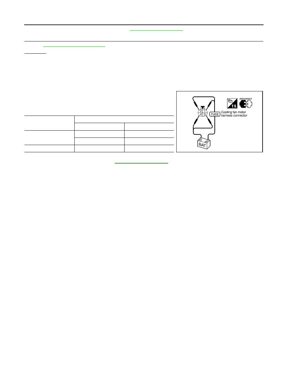
1. Disconnect cooling fan motor harness connector.
2. Supply cooling fan motor terminals with battery voltage and
check operation.
Cooling fan motor should operate.
If NG, replace cooling fan motor. Refer to
Cooling fan speed
Cooling fan motor terminals
(+)
(
−
)
Low
1
3 and 4
2
3 and 4
High
1 and 2
3 and 4
SEF734W
August 2012
2012 Pathfinder

ELECTRICAL LOAD SIGNAL
EC-923
< DTC/CIRCUIT DIAGNOSIS >
[VK56DE]
C
D
E
F
G
H
I
J
K
L
M
A
EC
N
P
O
ELECTRICAL LOAD SIGNAL
Description
INFOID:0000000007358841
The electrical load signal (Headlamp switch signal, etc.) is transferred via the CAN communication line.
Diagnosis Procedure
INFOID:0000000007358842
1.
CHECK LOAD SIGNAL CIRCUIT OVERALL FUNCTION-I
1. Turn ignition switch ON.
2. Connect CONSULT and select “DATA MONITOR” mode.
3. Select “LOAD SIGNAL” and check indication under the following conditions.
OK or NG
OK
>> GO TO 2.
NG
>> GO TO 4.
2.
CHECK LOAD SIGNAL CIRCUIT OVERALL FUNCTION-II
Check “LOAD SIGNAL” indication under the following conditions.
OK or NG
OK
>> GO TO 3.
NG
>> GO TO 5.
3.
CHECK HEATER FAN SIGNAL CIRCUIT OVERALL FUNCTION
Select “HEATER FAN SW” and check indication under the following conditions.
OK or NG
OK
>>
INSPECTION END
NG
>> GO TO 6.
4.
CHECK REAR WINDOW DEFOGGER SYSTEM
>>
INSPECTION END
5.
CHECK HEADLAMP SYSTEM
>>
INSPECTION END
6.
CHECK HEATER FAN CONTROL SYSTEM
HAC-4, "How to Perform Trouble Diagnosis For Quick And Accurate Repair"
Perform Trouble Diagnosis For Quick And Accurate Repair"
.
Condition
Indication
Rear window defogger switch: ON
ON
Rear window defogger switch: OFF
OFF
Condition
Indication
Lighting switch: ON at 2nd position
ON
Lighting switch: OFF
OFF
Condition
Indication
Heater fan control switch: ON
ON
Heater fan control switch: OFF
OFF
August 2012
2012 Pathfinder
EC-924
< DTC/CIRCUIT DIAGNOSIS >
[VK56DE]
ELECTRICAL LOAD SIGNAL
>>
INSPECTION END
August 2012
2012 Pathfinder
FUEL INJECTOR
EC-925
< DTC/CIRCUIT DIAGNOSIS >
[VK56DE]
C
D
E
F
G
H
I
J
K
L
M
A
EC
N
P
O
FUEL INJECTOR
Component Description
INFOID:0000000007358843
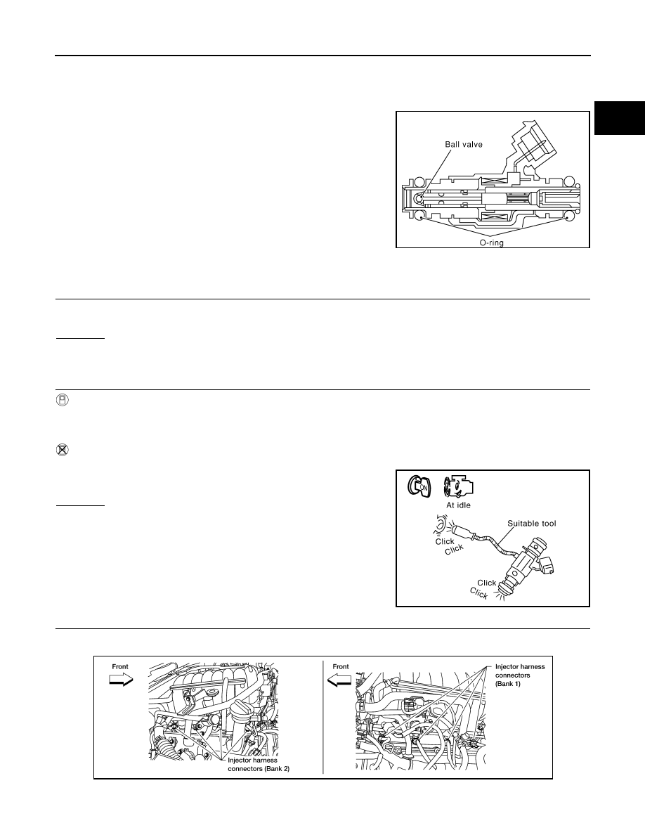
The fuel injector is a small, precise solenoid valve. When the ECM
supplies a ground to the fuel injector circuit, the coil in the fuel injec-
tor is energized. The energized coil pulls the ball valve back and
allows fuel to flow through the fuel injector into the intake manifold.
The amount of fuel injected depends upon the injection pulse dura-
tion. Pulse duration is the length of time the fuel injector remains
open. The ECM controls the injection pulse duration based on
engine fuel needs.
Diagnosis Procedure
INFOID:0000000007358844
1.
INSPECTION START
Turn ignition switch to START.
Are any cylinders ignited?
Yes or No
Yes
>> GO TO 2.
No
>> GO TO 3.
2.
CHECK OVERALL FUNCTION
With CONSULT
1. Start engine.
2. Perform “POWER BALANCE” in “ACTIVE TEST” mode with CONSULT.
3. Check that each circuit produces a momentary engine speed drop.
Without CONSULT
1. Start engine.
2. Listen to each fuel injector operating sound.
Clicking noise should be heard.
OK or NG
OK
>>
INSPECTION END
NG
>> GO TO 3.
3.
CHECK FUEL INJECTOR POWER SUPPLY CIRCUIT
1. Turn ignition switch OFF.
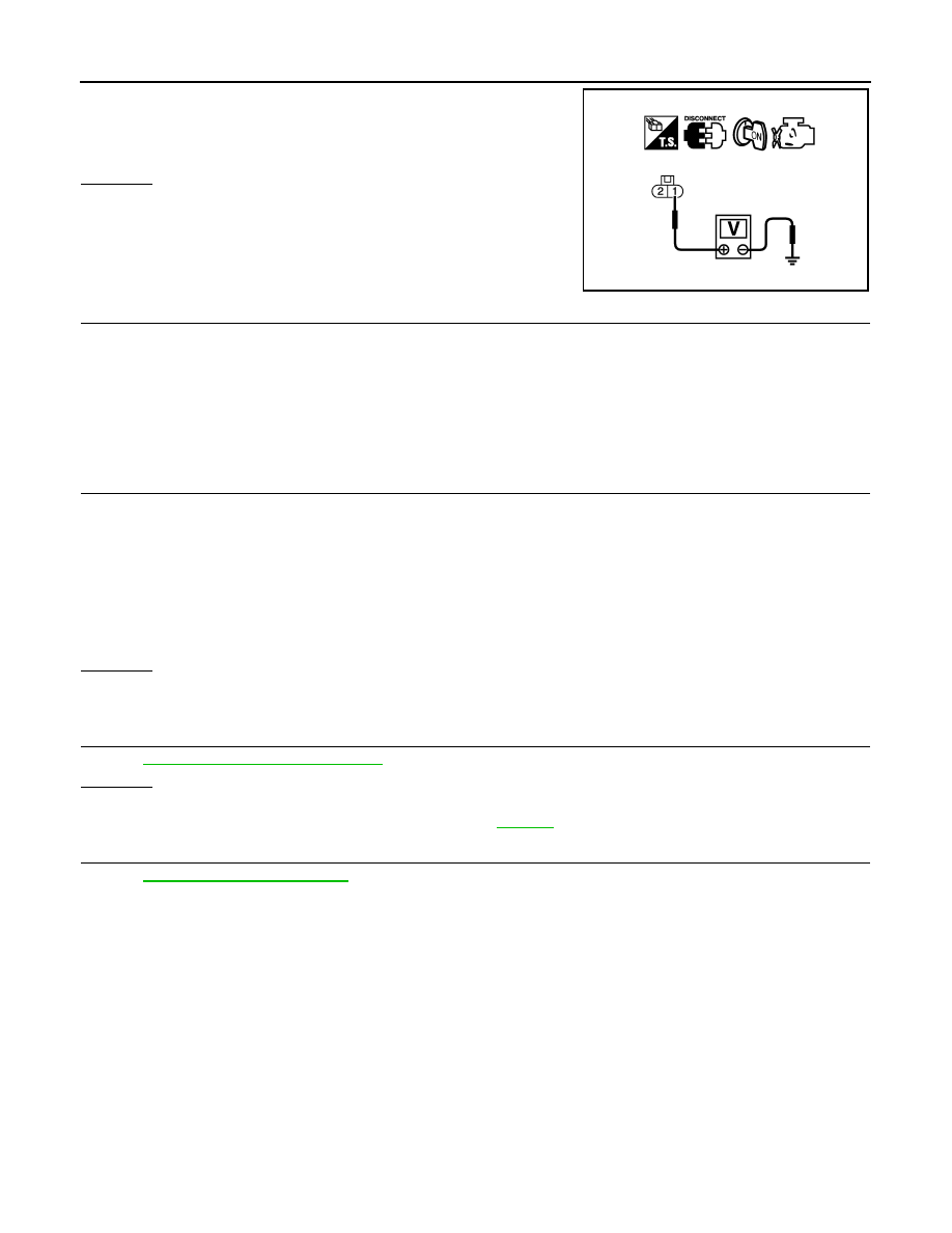
2. Disconnect fuel injector harness connector.
3. Turn ignition switch ON.
SEF375Z
PBIB1986E
BBIA0374E
August 2012
2012 Pathfinder
EC-926
< DTC/CIRCUIT DIAGNOSIS >
[VK56DE]
FUEL INJECTOR
4. Check voltage between fuel injector terminal 1 and ground with
CONSULT or tester.
OK or NG
OK
>> GO TO 5.
NG
>> GO TO 4.
4.
DETECT MALFUNCTIONING PART
Check the following.
• Harness connectors E2, F32
• IPDM E/R connector E119
• 15 A fuse (No. 55)
• Harness for open or short between fuel injector and fuse
>> Repair harness or connectors.
5.
CHECK FUEL INJECTOR OUTPUT SIGNAL CIRCUIT FOR OPEN AND SHORT
1. Turn ignition switch OFF.
2. Disconnect ECM harness connector.
3. Check harness continuity between fuel injector terminal 2 and ECM terminals 21, 22, 23, 40, 41, 42, 44,
63.
Refer to Wiring Diagram.
4. Also check harness for short to ground and short to power.
OK or NG
OK
>> GO TO 6.
NG
>> Repair open circuit or short to ground or short to power in harness or connectors.
6.
CHECK FUEL INJECTOR
EC-926, "Component Inspection"
OK or NG
OK
>> GO TO 7.
NG
>> Replace malfunctioning fuel injector. Refer to
.
7.
CHECK INTERMITTENT INCIDENT
GI-37, "Intermittent Incident"
>>
INSPECTION END
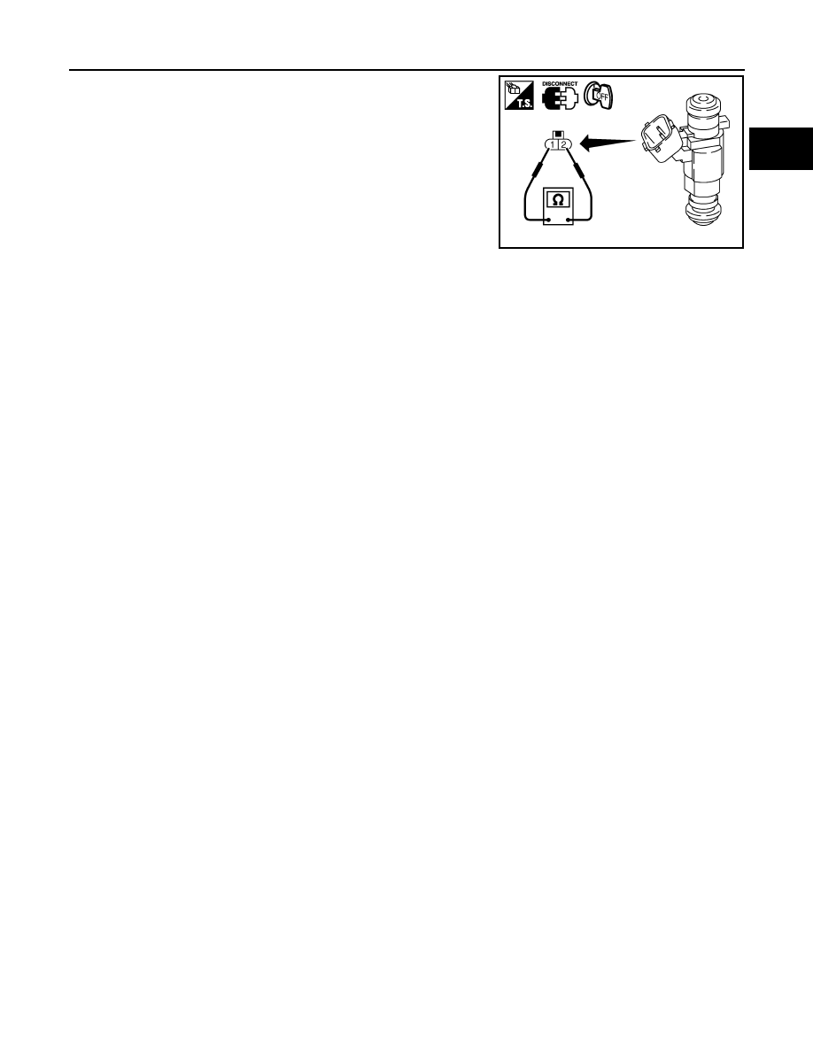
Component Inspection
INFOID:0000000007358845
FUEL INJECTOR
1. Disconnect fuel injector harness connector.
Voltage: Battery voltage
PBIB0582E
Continuity should exist.
August 2012
2012 Pathfinder
FUEL INJECTOR
EC-927
< DTC/CIRCUIT DIAGNOSIS >
[VK56DE]
C
D
E
F
G
H
I
J
K
L
M
A
EC
N
P
O
2. Check resistance between terminals as shown in the figure.
Resistance: 11.1 - 14.5
Ω
[at 10 - 60
°
C (50 - 140
°
F)]
PBIB1727E
August 2012
2012 Pathfinder
EC-928
< DTC/CIRCUIT DIAGNOSIS >
[VK56DE]
FUEL PUMP
FUEL PUMP
Description
INFOID:0000000007358846
SYSTEM DESCRIPTION
*: ECM determines the start signal status by the signals of engine speed and battery voltage.
The ECM activates the fuel pump for several seconds after the ignition switch is turned ON to improve engine
start ability. If the ECM receives a engine speed signal from the camshaft position sensor (PHASE), it knows
that the engine is rotating, and causes the pump to operate. If the engine speed signal is not received when
the ignition switch is ON, the engine stalls. The ECM stops pump operation and prevents battery discharging,
thereby improving safety. The ECM does not directly drive the fuel pump. It controls the ON/OFF fuel pump
relay, which in turn controls the fuel pump.
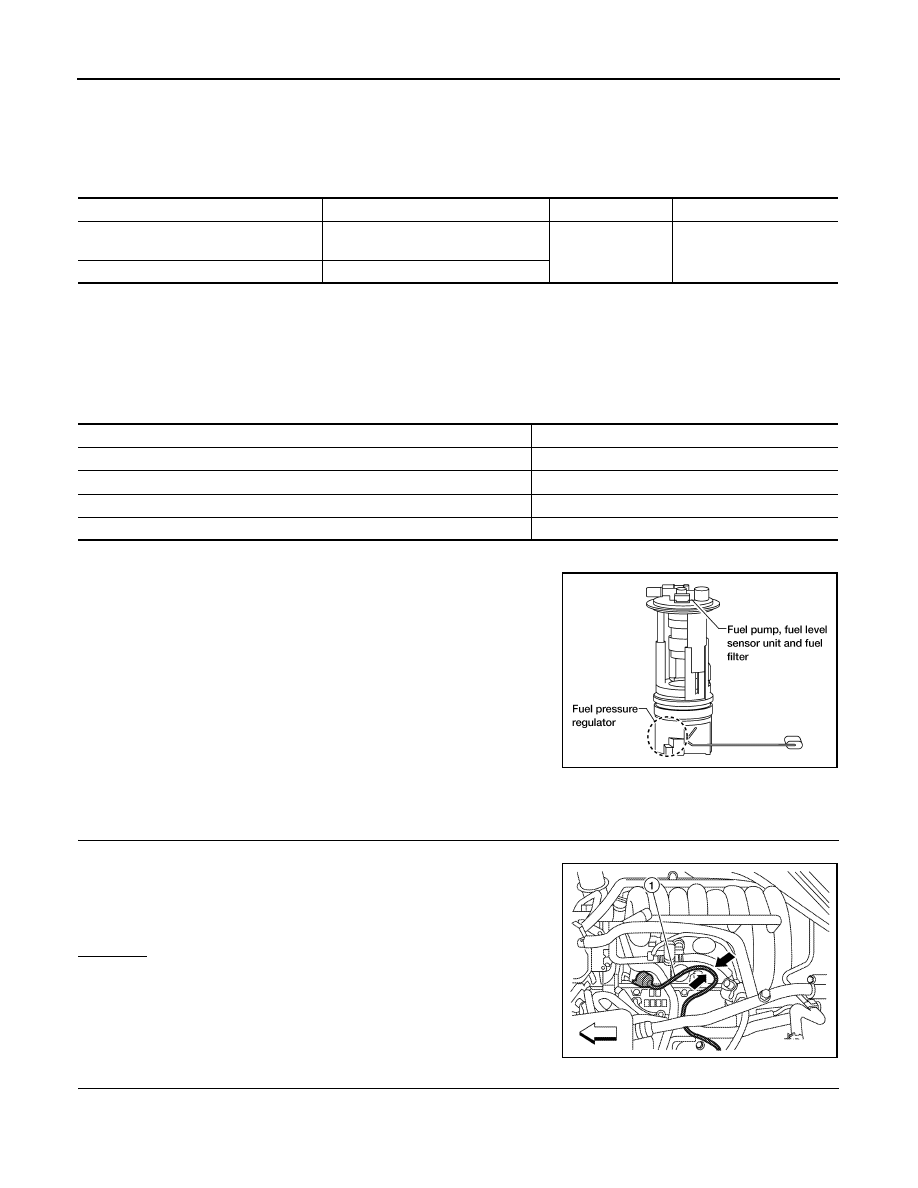
COMPONENT DESCRIPTION
A turbine type design fuel pump is used in the fuel tank.
Diagnosis Procedure
INFOID:0000000007358847
1.
CHECK OVERALL FUNCTION
1. Turn ignition switch ON.
2. Pinch fuel feed hose with two fingers.
OK or NG
OK
>>
INSPECTION END
NG
>> GO TO 2.
2.
CHECK FUEL PUMP POWER SUPPLY CIRCUIT-I
1. Turn ignition switch OFF.
2. Disconnect ECM harness connector.
3. Turn ignition switch ON.
Sensor
Input signal to ECM
ECM function
Actuator
Crankshaft position sensor (POS)
Camshaft position sensor (PHASE)
Engine speed*
Fuel pump control
Fuel pump relay
Battery
Battery voltage*
Condition
Fuel pump operation
Ignition switch is turned to ON
Operates for 1 second.
Engine running and cranking
Operates.
When engine is stopped
Stops in 1.5 seconds.
Except as shown above
Stops.
BBIA0529E
Fuel pressure pulsation should be felt on the fuel feed
hose for 1 second after ignition switch is turned ON.
ALBIA0356ZZ
August 2012
2012 Pathfinder
Нет комментариевНе стесняйтесь поделиться с нами вашим ценным мнением.
Текст